Control technology of environment-friendly biogas generating system
A biogas generation and environmental protection technology, applied in the direction of gas production bioreactors, biological sludge treatment, etc., can solve the problems of adjusting the amount and time of incoming and outgoing materials, uncontrollable incoming and outgoing materials, etc., and achieve the effect of automatic and convenient addition and remarkable effect
- Summary
- Abstract
- Description
- Claims
- Application Information
AI Technical Summary
Problems solved by technology
Method used
Image
Examples
Embodiment 1
[0037] A control process of an environment-friendly biogas generating system, comprising: automatically realizing material feeding and discharging after pretreatment by the biogas generating system.
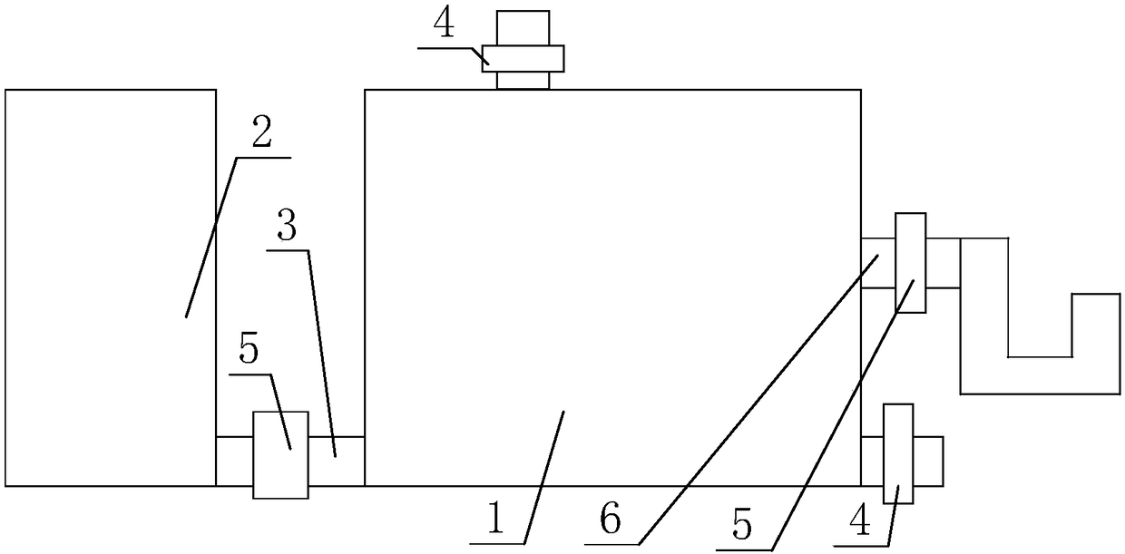
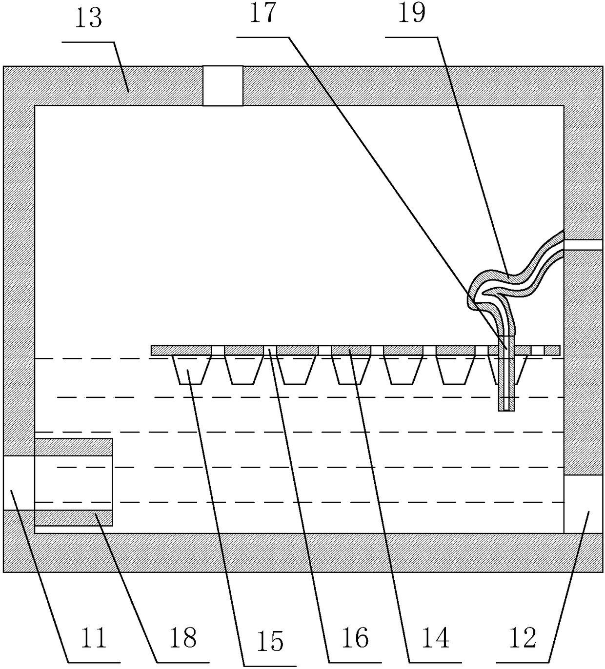
[0038] Among them, such asfigure 1 with figure 2 As shown, the biogas generation system includes a biogas digester 1, a feces storage tank 2 communicated with the biogas digester 1, and the biogas digester 1 includes a biogas digester body 13 having an exhaust port, a feed port 11 and a discharge port 12; The feed port 11 in the biogas digester body 13 is connected with a feed pipe 18 extending into the bottom of the biogas digester body 13;
[0039] The material outlet of the feces storage tank 2 is communicated with the feed port 11 through the connecting pipe 3; an overflow device is installed in the biogas tank body 13, and an overflow port is provided on the top of the biogas tank body 13; the overflow device includes An overflow pipe with one port extending into the bioga...
Embodiment 2
[0054] The difference between this embodiment and Embodiment 1 is that the structure of the overflow device is further optimized in this embodiment, and the specific settings are as follows:
[0055] The overflow device also includes a floating plate 14 placed on the surface of the biogas slurry in the biogas tank body 13, and a float 15 fixed below the floating plate 14; the overflow pipe includes an overflow that runs through the floating plate 14 and extends into the biogas slurry Pipe 17, and a connecting hose 19 with one end in communication with the top port of the overflow inner pipe 17 and the other end in communication with the overflow port; the overflow inner pipe 17 is fixed on the floating plate 14 and is set to extend into the biogas slurry The length of the overflow inner pipe 17 is L, and then L is less than 20cm.
[0056] Through the setting of the structure of the present invention, the scum in the biogas slurry can be effectively isolated and the discharge o...
Embodiment 3
[0058] The difference between this embodiment and Embodiment 2 is that the structures of the floating plate 14, the float 15 and the connecting hose 19 are further optimized in this embodiment, and the specific settings are as follows:
[0059] There are a plurality of floats 15 below the floating plate 14 , and the floats 15 are in a conical structure with a large top and a small bottom, and vent holes 16 are arranged on the floating plate 14 between the floats 15 . The floating plate 14 is made of a hard plastic plate, and the float 15 is made of foamed plastic, and the floating plate 14 floats on the surface of the biogas slurry through the action of the float 15 .
[0060] The connecting hose 19 is a stainless steel metal hose, and the length of the connecting hose 19 is the same as the height of the inner wall of the biogas digester body 13 . The length of the L is 5-10 cm, and the height of the float 15 is at least 1 cm smaller than the L.
[0061] Through the setting o...
PUM
| Property | Measurement | Unit |
|---|---|---|
| length | aaaaa | aaaaa |
Abstract
Description
Claims
Application Information
 - R&D
- Intellectual Property
- Life Sciences
- Materials
- Tech Scout
- Unparalleled Data Quality
- Higher Quality Content
- 60% Fewer Hallucinations
Browse by: Latest US Patents, China's latest patents, Technical Efficacy Thesaurus, Application Domain, Technology Topic, Popular Technical Reports.
© 2025 PatSnap. All rights reserved.Legal|Privacy policy|Modern Slavery Act Transparency Statement|Sitemap|About US| Contact US: help@patsnap.com


