
Eureka
For R&D, Eureka makes reading and utilizing patents & technical documents easy.
Eureka AIR
Designed for self-driven R&D workflows. Generate viable solutions, solve complex R&D challenges, empower your innovation with AI.

Eureka Materials
Designed for material experts only. Revolutionize your material R&D, from search, analyze, to developing new materials.

TechResearch
Generate reliable direction feasibility study reports for your R&D in just a few steps.

TechSeek
Discover and master advanced knowledge NOW. Basics, ideas, possibilities, all at once.

TechMind
As an expert in R&D Theories, TechMind can generates customized viable solutions instantly.

TechRisk
Analyze your overall solution with one click, know your potential R&D risks in advance.

TechMonitor
Get weekly tech updates, stay abreast of the latest tech innovations and key insights.
Radiation rate control device and radiation rate control method
A control device, emissivity technology, applied in the field of emissivity control device, can solve problems such as change
- Summary
- Abstract
- Description
- Claims
- Application Information
AI Technical Summary
Problems solved by technology
Method used
Image

Examples
Embodiment 1
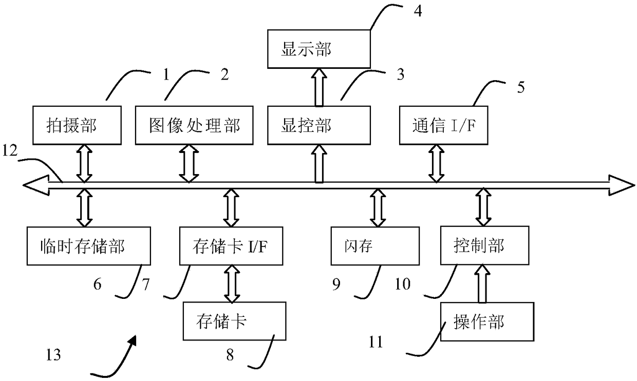
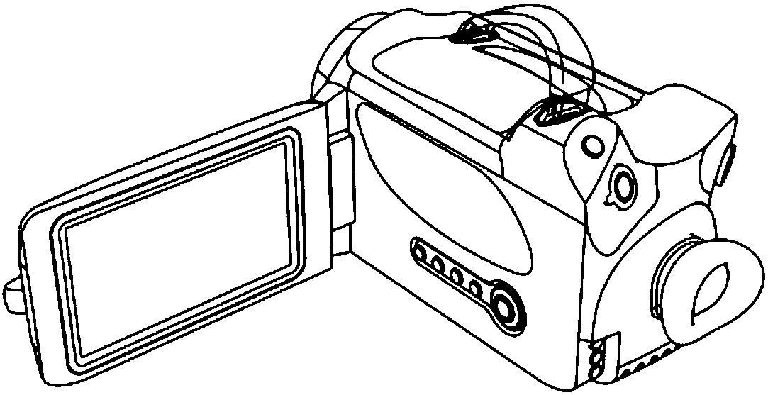
[0029] Embodiment 1 uses a portable thermal imaging device 13 with a shooting function as an example of an emissivity control device. refer to figure 1 Next, the structure of the thermal imaging device 13 will be described. The thermal imaging device 13 has a photographing part 1, an image processing part 2, a display and control part 3, a display part 4, a communication I / F5, a temporary storage part 6, a memory card I / F7, a memory card 8, a flash memory 9, an operation part 10, The control unit 11 is responsible for overall control of the thermal imaging device 13 by connecting the control and data bus 12 with the above corresponding parts.
[0030] The imaging unit 1 is composed of unillustrated optical components, lens driving components, infrared detectors, signal preprocessing circuits, and the like. The optics consist of an infrared optical lens for focusing the received infrared radiation onto the infrared detector. The lens driving part drives the lens to perform f...
Embodiment 2
[0056] Embodiment 2, relates to the measurement of 2 kinds of materials, reference Figure 6-Figure 7 , to illustrate embodiment 2;
[0057] Such as Figure 7 As shown, in the experiment, heating of material 1 and material 2 is involved. For example, the analysis area S01\S02 for material 1 and material 2 can be preset respectively; and the associated material type can be selected according to the analysis area S01\S02;
[0058] Step C01, taking pictures to obtain thermal image data;
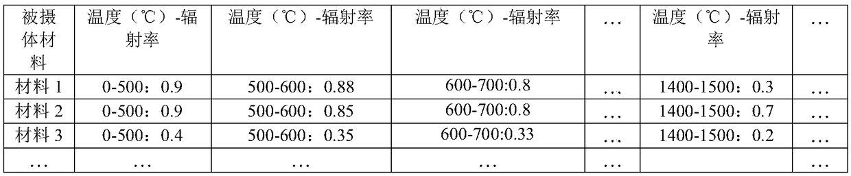
[0059] Step C02, according to the first emissivity of the material in each analysis area, measure and obtain the temperature value of each analysis area; in the initial test state, the default emissivity such as 0.9 can be used as the first emissivity to calculate the new shooting In the obtained thermal image data, the respective temperature values of material 1 and material 2;
[0060] Step C03, the temperature value will be obtained according to the first emissivity measurement, and comp...
Embodiment 3
[0066] Embodiments of the present invention are not limited to portable thermal imaging devices, and can also be applied to various online thermal imaging devices; Applied to thermal image processing devices that receive and process thermal image data from the outside.
[0067] Such as Figure 8-Figure 9 As shown, a thermal image processing device such as a computer, a personal digital assistant, a display device used in conjunction with a thermal image capture device with a shooting function, etc., as an example of an emissivity control device, is used to determine the emissivity of the acquired thermal image data and analysis.
[0068] refer to Figure 8 It is a block diagram of an implementation of an electrical structure of a thermal image processing system formed by connecting the emissivity control device 100 (thermal image processing device 100 ) and the thermal image shooting device 101 .
[0069] The thermal image processing device 100 has a communication interface...
PUM
 Abstract
Description
Claims
Application Information
 - R&D Engineer
- R&D Manager
- IP Professional
- Industry Leading Data Capabilities
- Powerful AI technology
- Patent DNA Extraction
Browse by: Latest US Patents, China's latest patents, Technical Efficacy Thesaurus, Application Domain, Technology Topic, Popular Technical Reports.
© 2024 PatSnap. All rights reserved.Legal|Privacy policy|Modern Slavery Act Transparency Statement|Sitemap|About US| Contact US: help@patsnap.com