Novel low-noise low-vibration permanent magnet motor stator rotor punching sheet

A permanent magnet motor and stator punching technology, which is applied in the direction of magnetic circuits, electric components, electrical components, etc., can solve the problems of electromagnetic noise and high vibration, reduce vibration and electromagnetic noise, improve torque constant, and meet the requirements of carrying capacity Effect

Pending Publication Date: 2018-07-31
JIANGSU FULIHUA GENERAL EQUIP
View PDF0 Cites 1 Cited by
  • Summary
  • Abstract
  • Description
  • Claims
  • Application Information

AI Technical Summary

Problems solved by technology

The magnetic flux generated by the stator energized conductor, due to the process error of the thickness of the punching material, the loss and burr difference of the punching sheet, the error of the lamination process, the lamination coefficient of the iron core is not greater than 1, and the magnetic resistance of the magnetic circuit flow direction, resulting in the air gap magnetic field The fluctuation of the permanent magnet motor makes the cogging torque of the permanent magnet motor too large. Combined with the effect of the transverse electromagnetic force on the current-carrying conductor, the current-carrying conductor will move relatively, forming electromagnetic noise, resulting in high electromagnetic noise and large vibration

Method used


Image

  • Novel low-noise low-vibration permanent magnet motor stator rotor punching sheet
  • Novel low-noise low-vibration permanent magnet motor stator rotor punching sheet
  • Novel low-noise low-vibration permanent magnet motor stator rotor punching sheet

Examples


Embodiment Construction

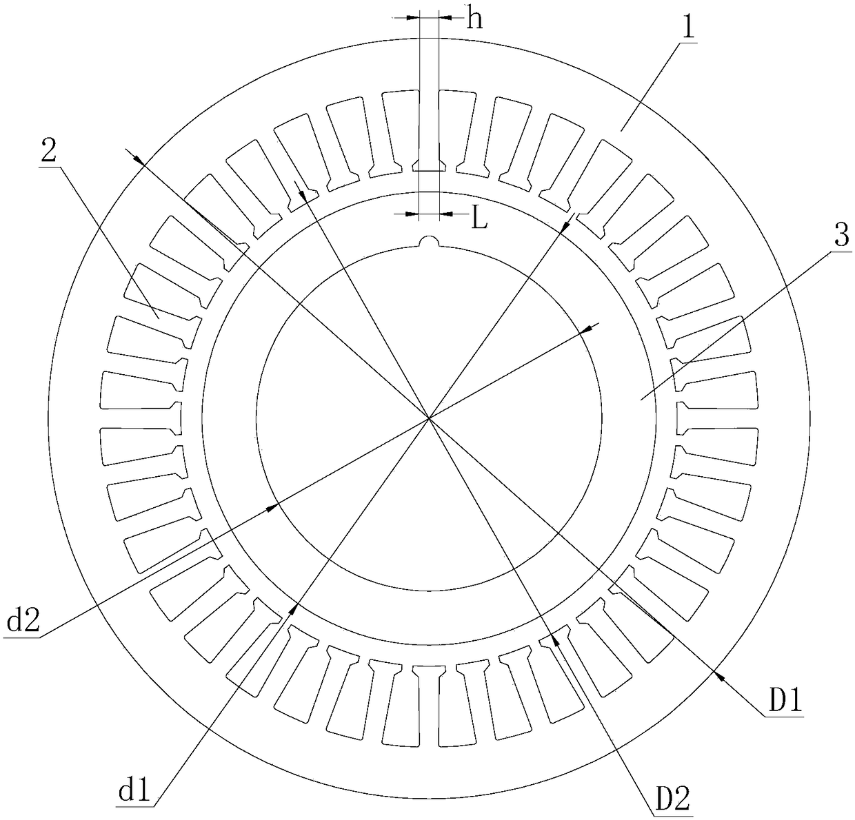
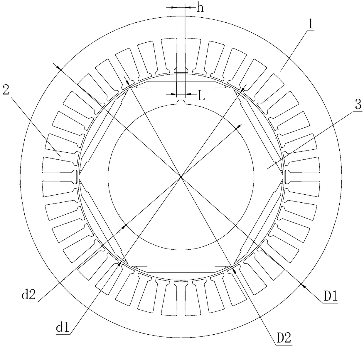
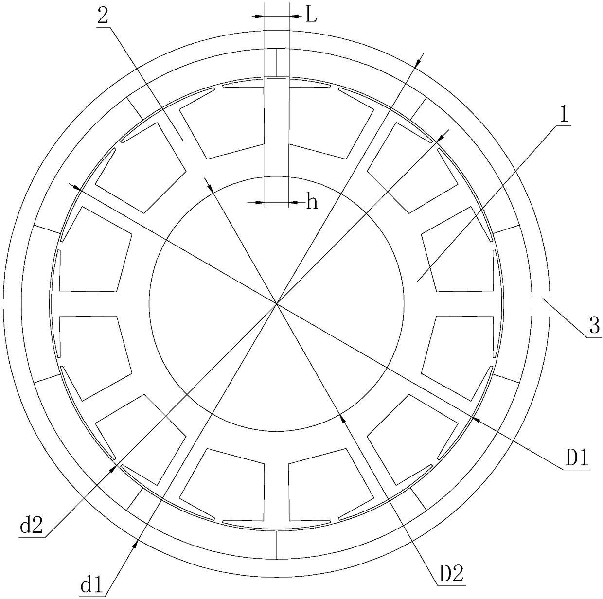
[0019] The technical solution of the present invention will be further described below in conjunction with the accompanying drawings.

[0020] see Figure 1-3 As shown, the above-mentioned stator and rotor stamping of a new type of low-noise and low-vibration permanent magnet motor, the stator stamping includes a stator yoke 1 whose magnetic density of the stator yoke is not greater than 1T, and the stator yoke 1 is larger than the average yoke of the existing stator yoke. The width of the part is at least 1.35 times. Considering the punching burrs are up to 0.054mm and the lamination coefficient is 0.9, the loss is up to 0.12, which is also 1.23 times wider than the existing stator yoke part, which can ensure that the magnetic circuit of the stator yoke part 1 will never be saturated. The stator punching sheet also includes a trapezoidal tooth portion 2 with a magnetic density of not more than 1.5T. The trapezoidal tooth portion 2 is at least 1.13 times wider than the average...


PUM


Abstract

The invention discloses a novel low-noise low-vibration permanent magnet motor stator rotor punching sheet. The novel low-noise low-vibration permanent magnet motor stator rotor punching sheet comprises a stator punching sheet and a thin-wall rotor punching sheet; the stator punching sheet comprises a stator yoke part with stator yoke part magnetic density of not greater than 1T and a trapezoid tooth part with the tooth part magnetic density of not greater than 1.5T, wherein the ratio of the tooth part magnetic density to the stator yoke part magnetic density is 1.5-1.6; the trapezoid tooth part is formed by inward extension from the inner side circumferential part of the stator yoke part in a radial direction; the trapezoid tooth part comprises short edges and long edges, the short edgesare positioned on the stator yoke part and the long edges are close to groove shoulders; the ratio of the long edges to the short edges is a, wherein a is greater than or equal to 1.06; and the thin-wall rotor punching sheet comprises a rotor yoke part with the rotor yoke part magnetic density of not greater than 1.2T, wherein the ratio of the tooth part magnetic density to the rotor yoke magneticdensity is 1.25-1.35. By virtue of the stator rotor punching sheet disclosed in the invention, magnetic resistance and transverse force displacement on a fastened and electrified conductor can be lowered, so that vibration and noise can be lowered; noise generated by power frequency current frequency and electromagnetic frequency resonance can be eliminated, so that vibration can be reduced; andan effective air-gap magnetic field can be smooth, so that cogging torque is lowered.

Description

technical field [0001] The invention relates to a stator and rotor stamping plate of a novel low-noise and low-vibration permanent magnet motor. Background technique [0002] In the existing permanent magnet motor, the flux density of the stator yoke is generally between 1.2-1.5T, and the flux density of the teeth is generally between 1.5-1.9T. The teeth have the same or different widths along their length direction. For teeth with unequal widths, the long side is located on the stator yoke, and the short side is the slot shoulder. The magnetic density of the rotor yoke is generally between 1.3-1.6T. The magnetic flux generated by the stator energized conductor, due to the process error of the thickness of the punching material, the loss and burr difference of the punching sheet, the error of the lamination process, the lamination coefficient of the iron core is not greater than 1, and the magnetic resistance of the magnetic circuit flow direction, resulting in the air gap ...

Claims


Application Information

Patent Timeline
Patent Type & Authority Applications(China)
IPC IPC(8): H02K1/14H02K1/22
CPCH02K1/146H02K1/22H02K2213/03
Inventor 沈坤华
Owner JIANGSU FULIHUA GENERAL EQUIP
Why Eureka
Try Eureka