Self-adaptive side sealing device for fuel gas blowing and control method thereof

A self-adaptive adjustment and sealing device technology, applied in the sintering field, can solve problems such as the side sealing device being stuck by the trolley, the negative impact on the sealing effect, and the large gap between the side sealing device and the trolley.

Pending Publication Date: 2018-08-03
ZHONGYE-CHANGTIAN INT ENG CO LTD
View PDF8 Cites 0 Cited by
  • Summary
  • Abstract
  • Description
  • Claims
  • Application Information

AI Technical Summary

Problems solved by technology

[0006] 1. Trolley deviation: When this abnormal working condition occurs, the sintering machine trolley will not be on the original track, but will deviate from the track to the left or right. At this time, if the gas injection side sealing device cannot quickly self-adapt Adjustment (the overall adjustment to the direction of the deviation of the trolley), will be stuck by the deviated trolley and run together with the trolley in the direction of the sintering machine, which will cause the gap between the gas pipeline and the gas injection hood, causing serious production accidents ;
[0007] 2. Outward tilting deformation of the trolley railing: When this abnormal working condition occurs, the overall railing of the sintering machine trolley is tilted outward, causing the width of the trolley to be larger than the original design width. At this time, if the gas injection side sealing device cannot quickly and automatically Adapt to the adjustment (the width of the device becomes larger), and the side seal device will be stuck by the trolley, which will cause serious production accide

Method used


Image

  • Self-adaptive side sealing device for fuel gas blowing and control method thereof
  • Self-adaptive side sealing device for fuel gas blowing and control method thereof
  • Self-adaptive side sealing device for fuel gas blowing and control method thereof

Examples


Embodiment approach

[0081] According to the second embodiment provided by the present invention, a control method of an self-adaptive adjustable side sealing device for gas injection is provided.

[0082] A control method of an adaptive adjustable side sealing device for gas injection or a method of using the side sealing device described in the first embodiment, the method includes the following steps:

[0083] 1) The sintering machine system starts to run, and the sintering machine trolley 1 moves forward;

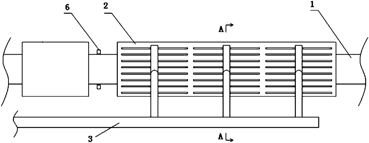
[0084] 2) The trolley health diagnosis device 6 monitors the status of the sintering machine trolley 1, and if it is running normally, it continues to run; if the sintering machine trolley 1 deviates, or the trolley bridges or collapses, then perform step 3);

[0085] 3) The trolley health diagnosis device 6 feeds back the monitored situation of the sintering machine trolley 1 to the control system 7, the control system 7 makes a judgment, diagnoses the condition of the sintering machine tr...

Embodiment 1

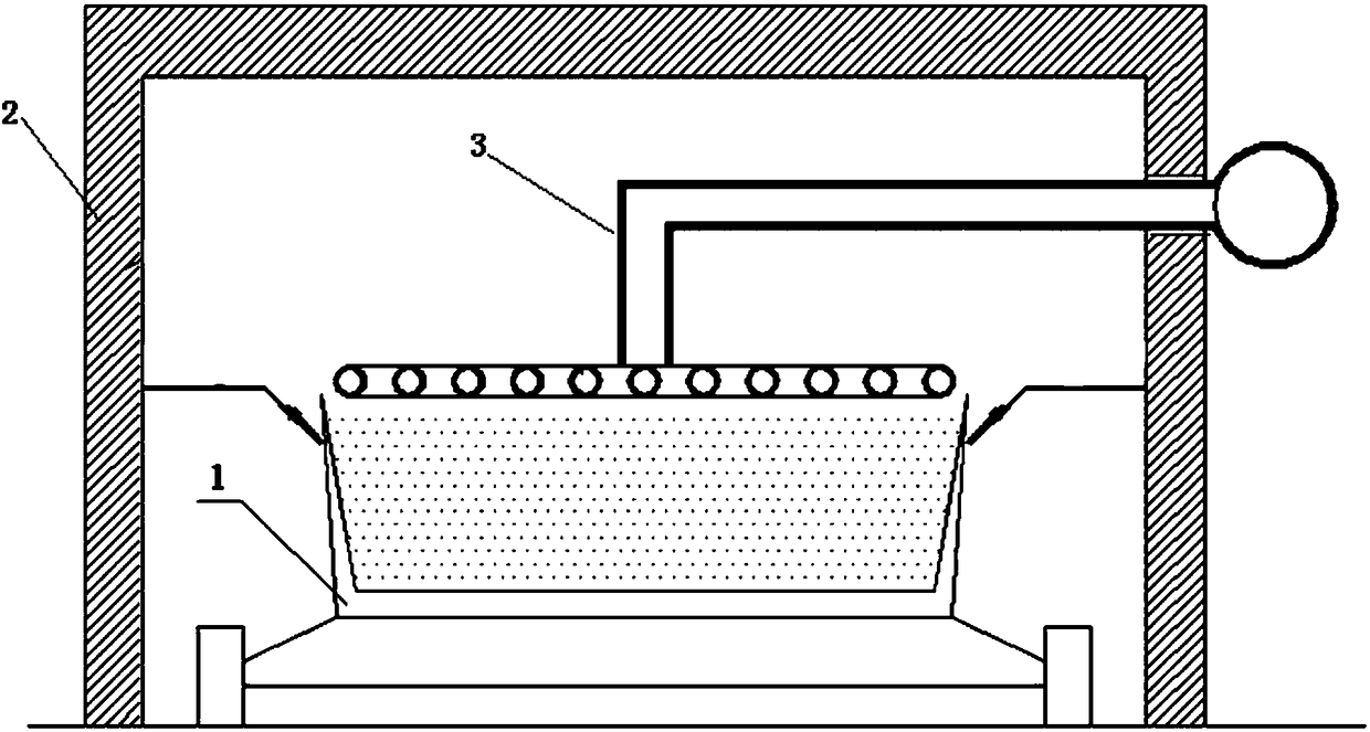
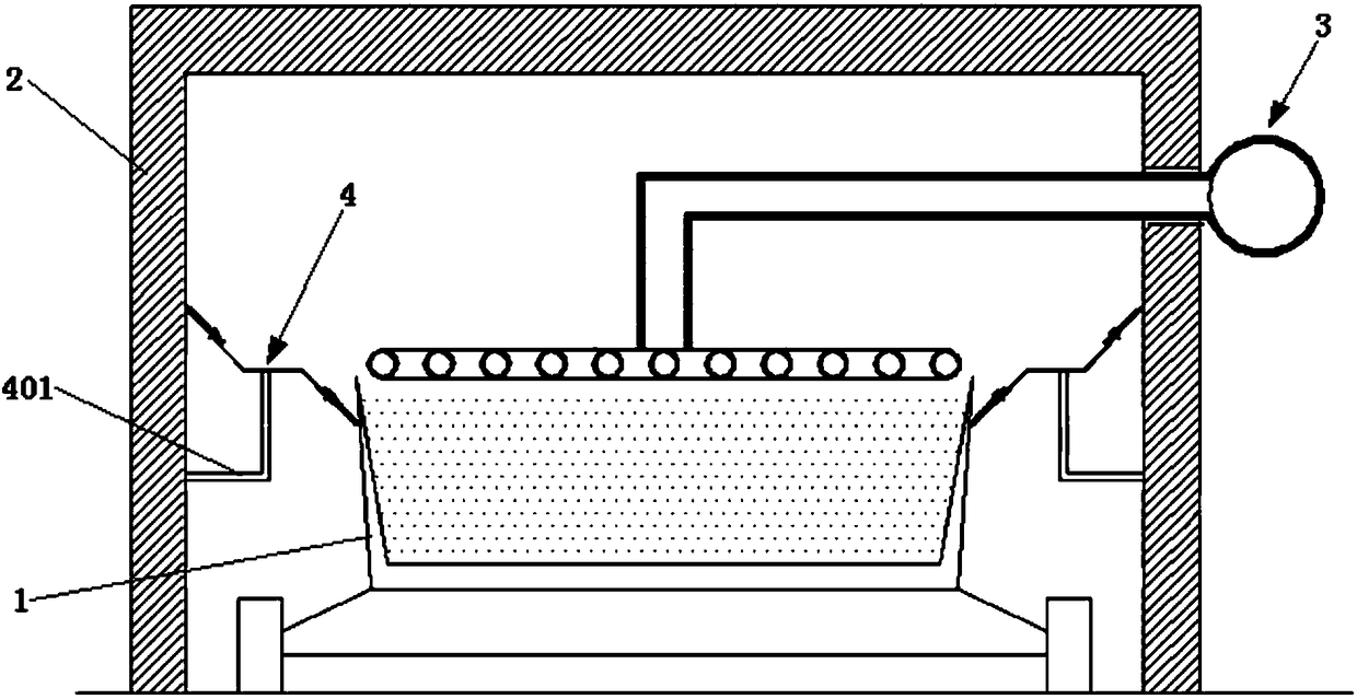
[0094] Such as image 3 As shown, an self-adaptive adjustable side sealing device for gas injection, the device includes a sintering machine trolley 1, a sealing cover 2, a gas injection device 3, and a side sealing device 4. The sintering machine trolley 1 is located in the sealed cover 2 . The gas injection device 3 is located above the sintering machine trolley 1 . The side sealing device 4 is a double-ended structure. The side sealing device 4 includes a fixing device 401 , a curved bearing plate 402 , an upper sealing plate 403 and a lower sealing plate 404 . The fixing device 401 is arranged inside the sealing cover 2 . The curved bearing plate 402 is connected with the fixing device 401 . The upper sealing plate 403 is connected with the upper end of the curved bearing plate 402 and is close to the inside of the sealing cover 2 . The lower sealing plate 404 is connected with the lower end of the curved bearing plate 402 and is close to the outer surface of the sint...

Embodiment 2

[0096] Such as Figure 4 and 5 As shown, embodiment 1 is repeated, except that the device also includes a position adjustment device 5 . The position adjustment device 5 includes a left and right adjustment plate 501 , a left and right adjustment rod 502 , an up and down adjustment plate 503 , and an up and down adjustment rod 504 . The up and down adjusting plate 503 is arranged inside the sealing cover 2 . One end of the up and down adjusting rod 504 is connected with the up and down adjusting plate 503 . The other end of the up and down adjusting rod 504 is connected with the left and right adjusting plate 501 . The bottoms of the left and right adjusting rods 502 are connected with the left and right adjusting plates 501 . The tops of the left and right adjusting rods 502 are connected with the curved bearing plate 402 .


PUM


Abstract

The invention relates to a self-adaptive side sealing device for fuel gas blowing. The device comprises a sintering machine trolley, a seal cover, a fuel gas blowing device and a side sealing device.The sintering machine trolley is located in the seal cover, the fuel gas blowing device is located above the sintering machine trolley, and the side sealing device is of a double-end type structure. The side sealing device comprises a fixing device, a curved bearing plate, an upper sealing plate and a lower sealing plate. The fixing device is arranged on the inner side of the seal cover, and the curved bearing plate is connected to the fixing device. The upper sealing plate is connected to the upper end of the curved bearing plate and is close to the inner side of the seal cover. The lower sealing plate is connected to the lower end of the curved beraing plate and is close to the outer side face of the sintering machine trolley. The double end sealing device capable of achieving real-timeself-adaptive adjustment achieves the purposes of stable production, smooth production and safe production of a whole fuel gas blowing assisted sintering production line.

Description

technical field [0001] The invention relates to a side sealing device and a control method thereof, in particular to an self-adaptive adjustable side sealing device for gas injection and a control method thereof, belonging to the technical field of sintering. Background technique [0002] The sintering process is a key link in the ironmaking process. Its principle is to mix various powdery iron-containing raw materials with an appropriate amount of fuel and flux, add an appropriate amount of water, mix and pelletize the material on the sintering equipment to make the material A series of physical and chemical changes, sintered into blocks, which are sent to the blast furnace for the next step. [0003] In order to reduce the coke ratio and smelting cost of blast furnace ironmaking, blast furnaces often require high strength and high reducibility for sinter. In the sintering process, the sintered ore is generally required to have high strength, high yield, low return rate, a...

Claims


Application Information

Patent Timeline
IPC IPC(8): F16J15/18F27B21/08F27B21/14
CPCF16J15/181F16J15/184F16J15/187F27B21/00F27M2003/04
Inventor 周浩宇刘前
Owner ZHONGYE-CHANGTIAN INT ENG CO LTD
Why Eureka
Try Eureka