Photoetching method and photoetching machine

A lithography machine and aperture technology, applied in the field of lithography, can solve the problem of low pattern contrast of dense patterns in lithography, and achieve the effects of solving low pattern contrast, improving performance and ensuring uniformity

Inactive Publication Date: 2018-08-03
HUAIAN IMAGING DEVICE MFGR CORP
View PDF0 Cites 0 Cited by
  • Summary
  • Abstract
  • Description
  • Claims
  • Application Information

AI Technical Summary

Problems solved by technology

[0005] The problem solved by the embodiments of the present invention is the problem of low pattern contrast of photolithographic dense patterns

Method used


Image

  • Photoetching method and photoetching machine
  • Photoetching method and photoetching machine
  • Photoetching method and photoetching machine

Examples


Embodiment Construction

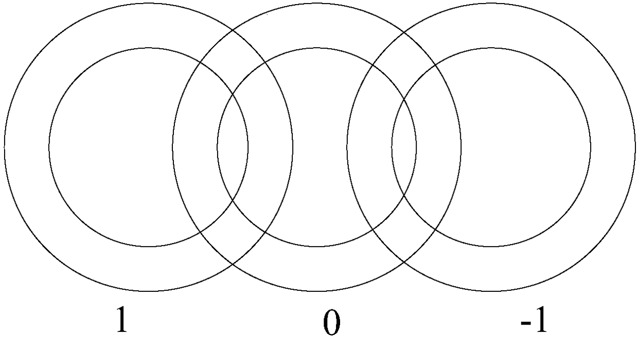
[0027] As mentioned above, existing photolithography suffers from low pattern contrast. To better explain the problem, refer to figure 1 The schematic diagram of the shape of the light source used for photolithography is shown.

[0028] like figure 1 As shown, the light emitted from the light source includes multi-level light after diffraction, such as 0-level light, 1-level light, 2-level light...etc. After filtering the light emitted by the light source with a diaphragm and an optical lens, the 0-order light and ±1-order light are reserved for photolithography.

[0029] It should be noted, figure 1 The two sides of the middle 0 aurora are graphics formed by 1st-level light and -1-level light, but the left and right positions of 1st-level light and -1-level light do not affect the actual lithography effect. This is artificial for easy understanding. Regulation. The reason is the same in the following description and examples.

[0030] figure 1 Shown are ring 0 and ring...


PUM


Abstract

Disclosed are a photoetching method and a photoetching machine. The photoetching machine comprises a light source, a baffle, a diaphragm, an optical element, a mask plate, a projection lens and a substrate which are arranged along an optical path in sequence; the diaphragm comprises a light-transmitting region; and the diaphragm is used for filtering light from the light source to enable the overlaid part of the 0-level light and 1-level light to pass through. By virtue of the scheme, the photoetching machine remains the overlaid part of the 0-level light and 1-level light and filters off thenon-overlaid part of the 0-level light and 1-level light, so that photoetching pattern uniformity can be further ensured and photoetching pattern contrast ratio is improved, thereby improving the performance of the photoetching machine.

Description

technical field [0001] Embodiments of the present invention relate to the field of lithography, and in particular, to a lithography method and a lithography machine. Background technique [0002] Currently used lithography machines use coaxial lighting as the lighting method. In order to reduce the line width of the process, the wavelength of the light used will be reduced as much as possible. However, if the light wavelength is too small, diffraction will occur, which will reduce the contrast of the photolithography pattern. Therefore, there is an off-axis lighting method. [0003] Off-axis illumination has a smaller linewidth and greater depth of focus without changing the wavelength of the light source. However, the off-axis illumination used in lithography must include different levels of light. If there is only one level of light, only the information of the intensity of the light can be obtained, but the image information of the light cannot be obtained. Therefore,...

Claims


Application Information

Patent Timeline
Patent Type & Authority Applications(China)
IPC IPC(8): G03F7/20
CPCG03F7/2002G03F7/70091
Inventor 龙海凤李天慧藤井光一
Owner HUAIAN IMAGING DEVICE MFGR CORP
Why Eureka
Try Eureka