Supercharge Your Innovation With Domain-Expert AI Agents!

Current-limiting reactor of three-phase wire shared magnetic ring

A technology of current-limiting reactors and phase conductors, used in circuits, electrical components, transformer/inductor magnetic cores, etc. Material saving effect

Pending Publication Date: 2018-08-03
SHENZHEN LIGAO ELECTRIC ENERGY TECH CO LTD
View PDF0 Cites 3 Cited by
  • Summary
  • Abstract
  • Description
  • Claims
  • Application Information

AI Technical Summary

Problems solved by technology

[0003] The technical problem to be solved by the present invention is to provide a current-limiting reactor with a shared magnetic ring for three-phase wires, which can improve the problems of large volume, heavy weight and high cost of existing current-limiting reactors, and can be connected in series with three-phase delta There will be no failure of current-limiting reactors when capacitor banks are connected in parallel

Method used


Image

  • Current-limiting reactor of three-phase wire shared magnetic ring
  • Current-limiting reactor of three-phase wire shared magnetic ring
  • Current-limiting reactor of three-phase wire shared magnetic ring

Examples


Embodiment 1

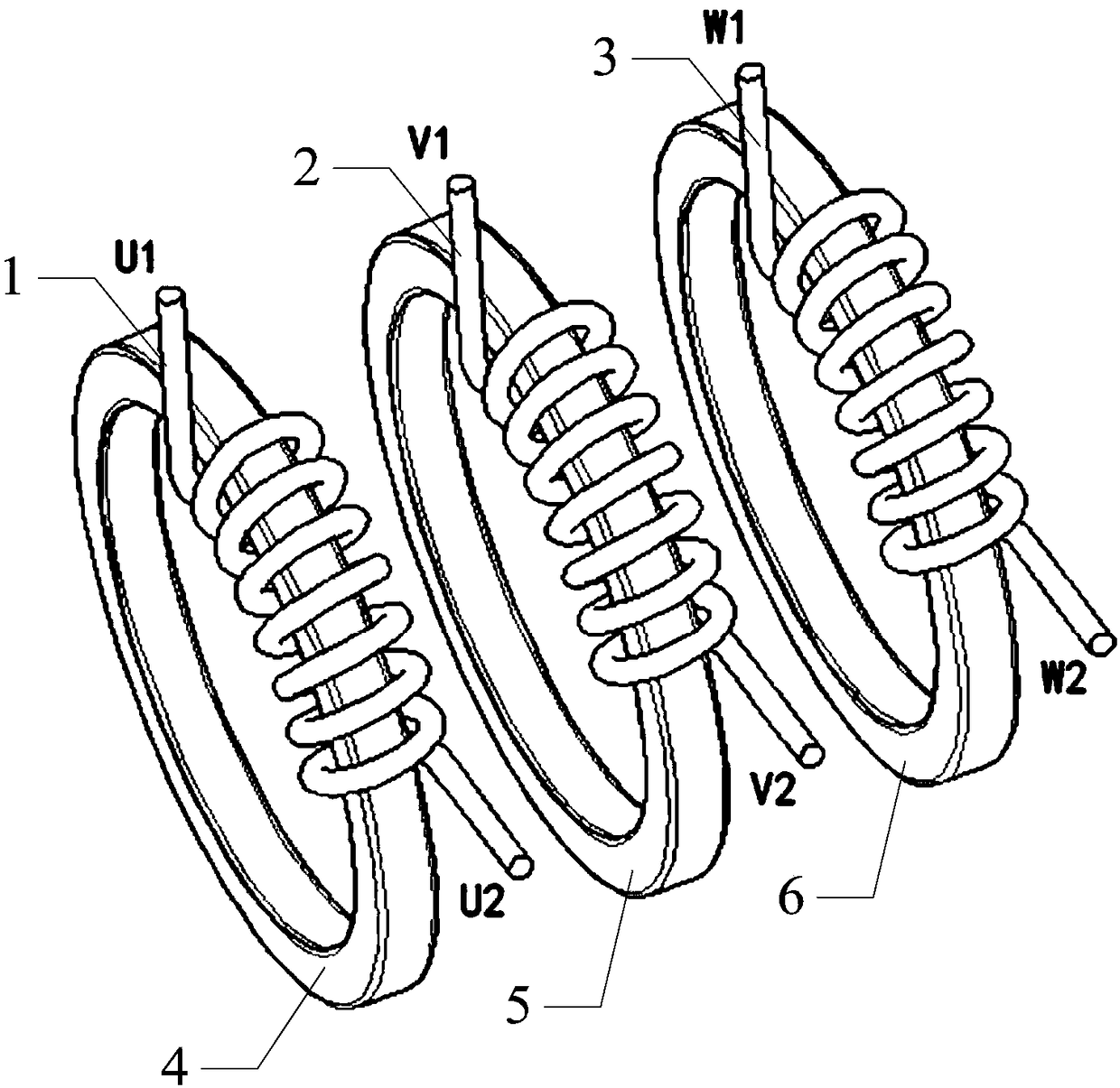
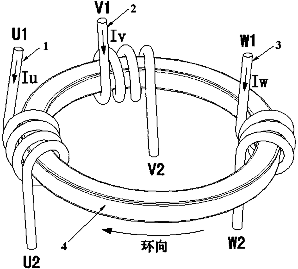
[0030] In this example, if image 3 As shown, three insulated wires 1, 2, and 3 with a length of 590mm and a wire diameter of 8 square millimeters are respectively wound on an amorphous magnetic ring 4 of 57×32×20 mm for 4 turns to form a A current-limiting reactor for three-phase conductors sharing a magnetic ring. The wire 1 is connected to the U terminal, the current Iu flows from the U1 terminal to the U2 terminal, and flows counterclockwise around the ring direction of the amorphous magnetic ring 4; the wire 2 is connected to the V terminal, and the current Iv flows from the V1 terminal to the V2 terminal, around The circumferential direction of the amorphous magnetic ring 4 flows in a clockwise direction; the wire 3 is connected to the W terminal, and the current Iw flows from the W1 terminal to the W2 terminal, and the circumferential direction around the amorphous magnetic ring 4 flows in a clockwise direction. The current-limiting reactor of the three-phase wires sha...

Embodiment 2

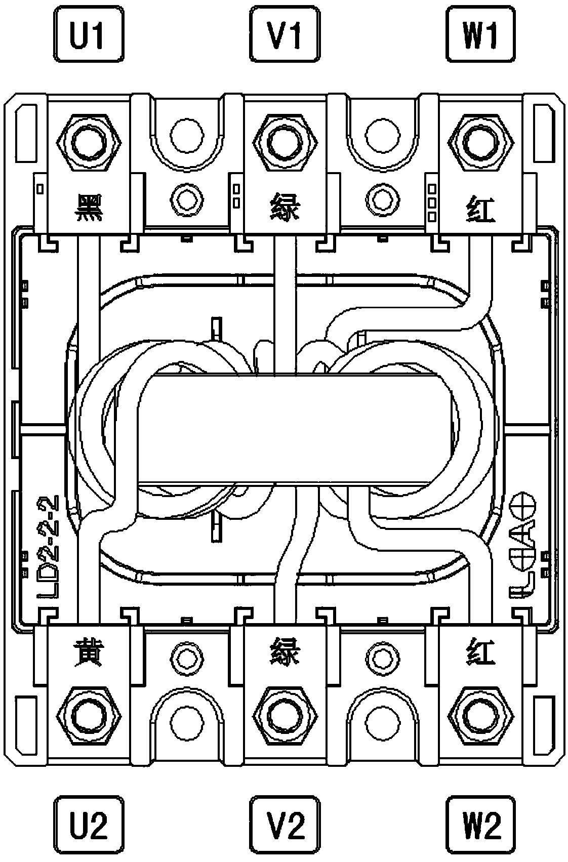
[0035] In another embodiment, such as Figure 4 As shown, three insulated wires 1, 2 and 3 with a length of 590 mm and a wire diameter of 8 square millimeters are respectively placed in a group of amorphous magnetic rings of 50 × 25 × 10 mm (composed of magnetic rings 4 and magnetic rings of the same specification) The ring 5 is superimposed) and 4 coils are wound on the top to form a current-limiting reactor in which the three-phase wires share the magnetic ring. The wire 1 is connected to the U terminal, the current Iu flows from the U1 terminal to the U2 terminal, and flows counterclockwise around the ring direction of the amorphous magnetic ring group; the wire 2 is connected to the V terminal, and the current Iv flows from the V1 terminal to the V2 terminal, around the The ring direction of the amorphous magnetic ring group flows clockwise; the wire 3 is connected to the W terminal, the current Iw flows from the W1 end to the W2 end, and the ring direction around the amor...


PUM


Abstract

The invention provides a current-limiting reactor of a three-phase wire shared magnetic ring. The structure of the current-limiting reactor comprises three phase wires, wherein the three phase wires are respectively connected with three phase voltages of an electrical system, and the three phase wires are wound around the same group of magnetic rings and are not connected to one another. The current-limiting reactor has the characteristics of simple structure, small size and light weight, the magnetic ring material is saved by one third compared with the prior art, and a three-phase three-wirecompensation loop wiring mode and a three-phase four-fire compensation loop wiring mode of a dynamic passive compensation device of the electrical system can be simultaneously met.

Description

technical field [0001] The invention relates to the technical field of low-voltage complete sets of reactive power compensation devices for power systems, in particular to a current-limiting reactor for three-phase wires sharing a magnetic ring. Background technique [0002] The current-limiting reactors used in the technical field of low-voltage complete sets of reactive power compensation devices in power systems mainly adopt two structures of iron core and hollow core, which are heavy, bulky and complicated to process. Due to its excellent electromagnetic properties (high saturation magnetic induction, low coercive force, high initial permeability), amorphous magnetic ring has been widely used in power electronics technology, anti-electromagnetic interference components, switching power supplies, sensors and other fields . At present, current-limiting reactors using amorphous magnetic rings generally use one-phase wires wound on a magnetic ring as a single-phase reactor,...

Claims


Application Information

Patent Timeline
IPC IPC(8): H01F27/24H01F27/28H01F27/32H02J3/18
CPCH02J3/18H01F27/24H01F27/28H01F27/2823H01F27/324Y02E40/30
Inventor 林川
Owner SHENZHEN LIGAO ELECTRIC ENERGY TECH CO LTD
Features
  • R&D
  • Intellectual Property
  • Life Sciences
  • Materials
  • Tech Scout
  • Unparalleled Data Quality
  • Higher Quality Content
  • 60% Fewer Hallucinations
Learn More