Charging generator

A charging machine and warehouse technology, applied in the direction of current collectors, electric vehicles, electrical components, etc., can solve the problems of heavy overall weight of the charging machine, high energy consumption of train operation, and large radiator, so as to reduce the energy consumption of train operation, Improved cooling efficiency and reduced weight

Pending Publication Date: 2018-08-03
苏州市万松电气有限公司
View PDF0 Cites 3 Cited by
  • Summary
  • Abstract
  • Description
  • Claims
  • Application Information

AI Technical Summary

Problems solved by technology

Chargers usually include charging circuits such as input circuits, full-bridge inverter circuits, output circuits, and control circuits, involving rectifier bridge modules, input contactors, filters, current limiting resistors, discharge resistors, input filter capacitors, IGBT modules, IGBT Snubber capacitors, voltage and current sensors, driver boards, main control boards, terminal blocks, high-frequency transformers, output filter inductors, filter capacitors, EMI filters and other devices, see Figure 8 , because some devices cannot be placed in a humid environment, it is usually necessary to use a closed cavity to achieve a high protection level. Because some devices have heat dissipation requirements, it is usually necessary to design a heat dissipation structure. Therefore, the existing charger The structure is to arrange many devices in a whole shell, and install a radiator on the back of the shell to adopt natural cooling, so the radiator is relatively large, and the volume of the charger is also large, resulting in the overall weight of the charger. Heavy, because the shells of chargers are mostly shells with high IP protection level requirements, especially for chargers used on trains such as high-speed rail and bullet trains. Therefore, it is necessary to design a new charger structure to achieve the purpose of reducing the volume and weight of the charger, which is conducive to the weight reduction of train equipment and the energy consumption of train operation.

Method used


Image

  • Charging generator
  • Charging generator
  • Charging generator

Examples


Embodiment Construction

[0019] In order to make the present invention more obvious and understandable, the specific implementation manners of the present invention will be described in detail below in conjunction with the accompanying drawings.

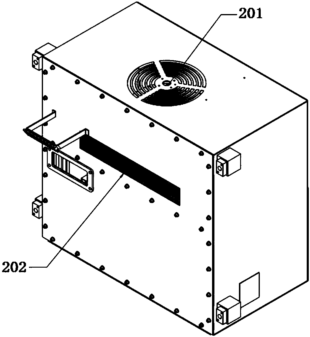
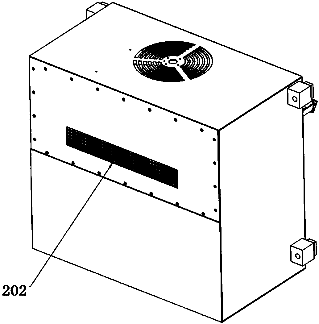
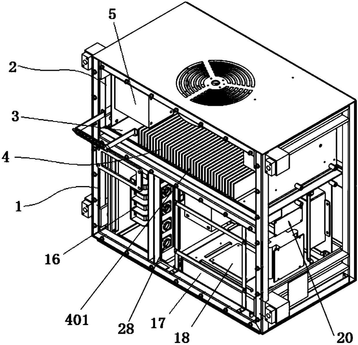
[0020] Such as figure 1 , image 3 and Figure 4 As shown, a charging machine includes a front compartment 1, a rear compartment 2 and a partition plate 3 separating the front compartment and the rear compartment, and also includes a radiator 4, which is installed At the mounting opening reserved on the partition plate, the radiator is mainly composed of a mounting surface 401 and a number of cooling fins 402 extending from the mounting surface. The gap between the radiator and the partition plate Preferably, the gap between the radiator and the partition plate is sealed with a sealant; the installation surface is arranged in the front compartment, and the cooling fins are arranged in the rear compartment. The shell forming the front compartment and the ...


PUM


Abstract

The invention discloses a charging generator. The charging generator comprises a front warehouse and a rear warehouse. The front chamber is used to install a device that requires IP protection in thecharging circuit of the charger. The rear chamber does not require an IP protection level and is used to install a device that does not require IP protection in the charging circuit of the charger. Inthis way, structural optimization of a plurality of devices involved in the charging circuit of the charger can be realized, thereby reducing the overall volume of the charger, thereby achieving thepurpose of reducing the overall weight of the charger. Specifically, a heat sink is installed on the partition plate between the front and rear chambers, and the mounting surface of the heat sink is placed in the front chamber, and the heat radiating fins of the heat sink are placed in the rear chamber, and install the fan and the air inlet and outlet in the back warehouse. In this way, efficientheat dissipation by the combination of the heat dissipating fins and the fan can greatly improve the heat dissipation efficiency and reduce the volume of the heat sink itself. In turn, the purpose ofreducing the overall volume of the charger is achieved, which is beneficial to the weight reduction of the train equipment and the reduction of the energy consumption of the train operation.

Description

technical field [0001] The invention relates to a charger for trains, in particular to a charger with miniaturization, low weight and high heat dissipation efficiency. Background technique [0002] The charger is used in all high-speed rail, bullet trains, vehicles and related facilities powered by batteries, and is an important power supply equipment. Chargers usually include charging circuits such as input circuits, full-bridge inverter circuits, output circuits, and control circuits, involving rectifier bridge modules, input contactors, filters, current limiting resistors, discharge resistors, input filter capacitors, IGBT modules, IGBT Snubber capacitors, voltage and current sensors, driver boards, main control boards, terminal blocks, high-frequency transformers, output filter inductors, filter capacitors, EMI filters and other devices, see Figure 8 , because some devices cannot be placed in a humid environment, it is usually necessary to use a closed cavity to achieve...

Claims


Application Information

Patent Timeline
IPC IPC(8): H02J7/00H05K7/20
CPCH02J7/0042H05K7/209H05K7/20909Y02E60/10
Inventor 洪振海杨磊张陈张松范跃坤潘贻丰
Owner 苏州市万松电气有限公司
Why Eureka
Try Eureka