Basement connection portion crack preventing structure

A cracked structure and basement technology, applied in underwater structures, infrastructure engineering, water conservancy projects, etc., can solve problems such as ineffectiveness, appearing in settlement joints, and difficult settlement joints, so as to strengthen adhesion, reduce Cracks, the effect of removing applied stress

Inactive Publication Date: 2018-08-07
浙江联建工程设计有限公司
View PDF6 Cites 4 Cited by
  • Summary
  • Abstract
  • Description
  • Claims
  • Application Information

AI Technical Summary

Problems solved by technology

[0005] However, for those skilled in the art of building construction, installing waterproof steel plates on the outer wall of the basement is a conventional technical means, which shows that it has a certain effect on the crack prevention and waterproofing of the basement, but there is no more prominent effect
Moreover, for the anti-cracking and waterproofing of the basement, due to the special location of the connecting part of the basement, it is generally designed as a corridor, which is the entrance and exit of the basement or the connection with other buildings, which is subject to more shear stress and no settlement When the settlement joints are used, the wall structure can hardly bear the shear force exerted by the overall superstructure, and through-cracks are extremely prone to appear. However, when settlement joints are set, the treatment of settlement joints is more difficult, and cracks and water seepage often appear at the settlement joints. At present, it is difficult to meet the requirements of crack resistance and waterproof only by the function of waterproof steel plate.

Method used


Image

  • Basement connection portion crack preventing structure
  • Basement connection portion crack preventing structure
  • Basement connection portion crack preventing structure

Examples


Embodiment

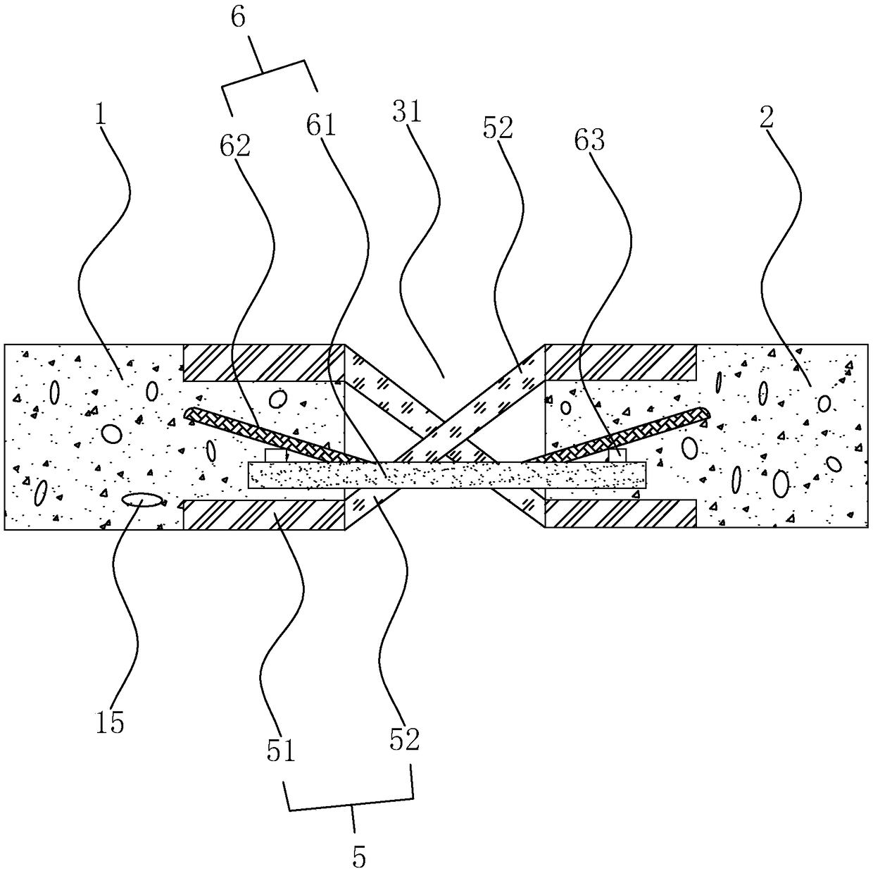
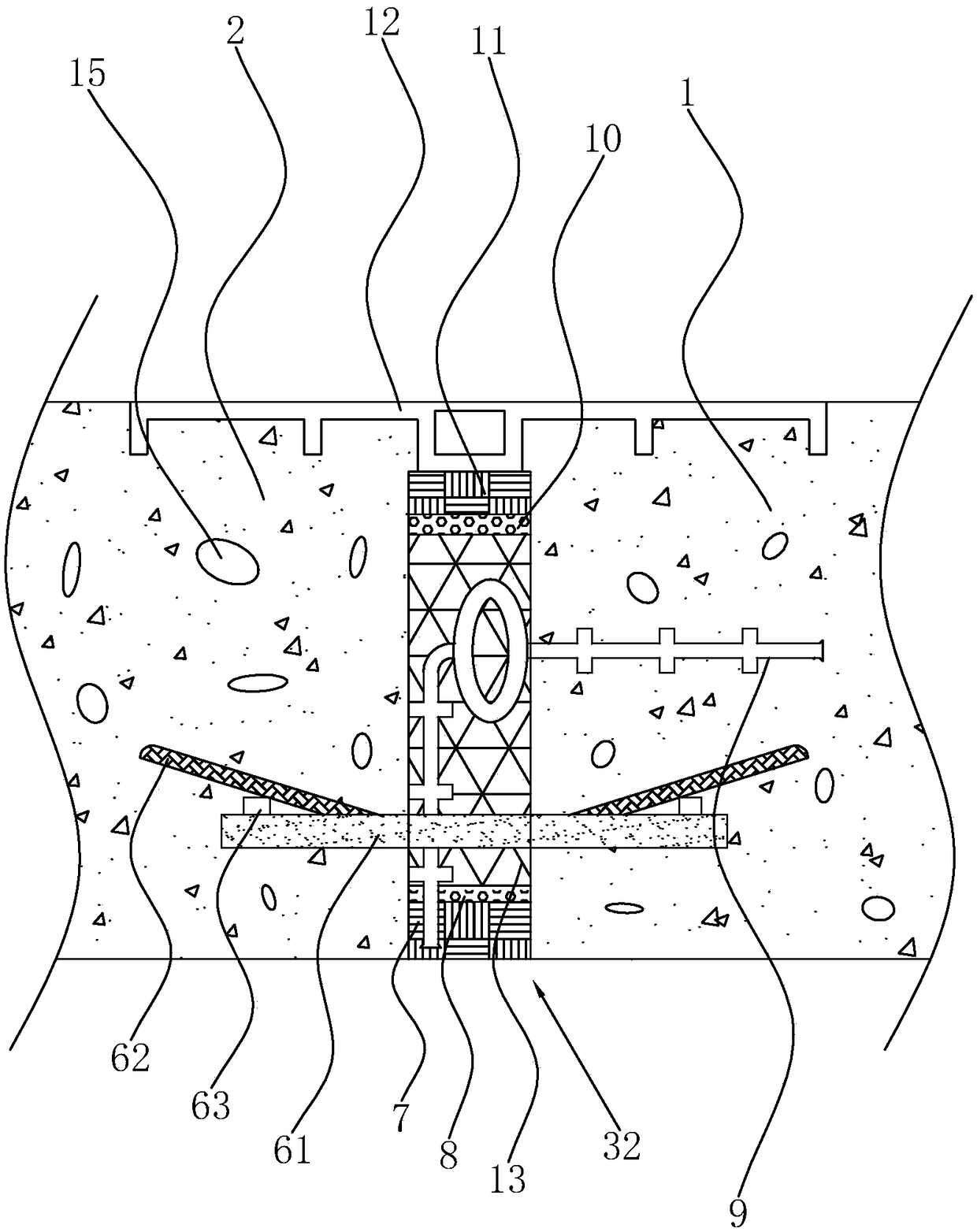
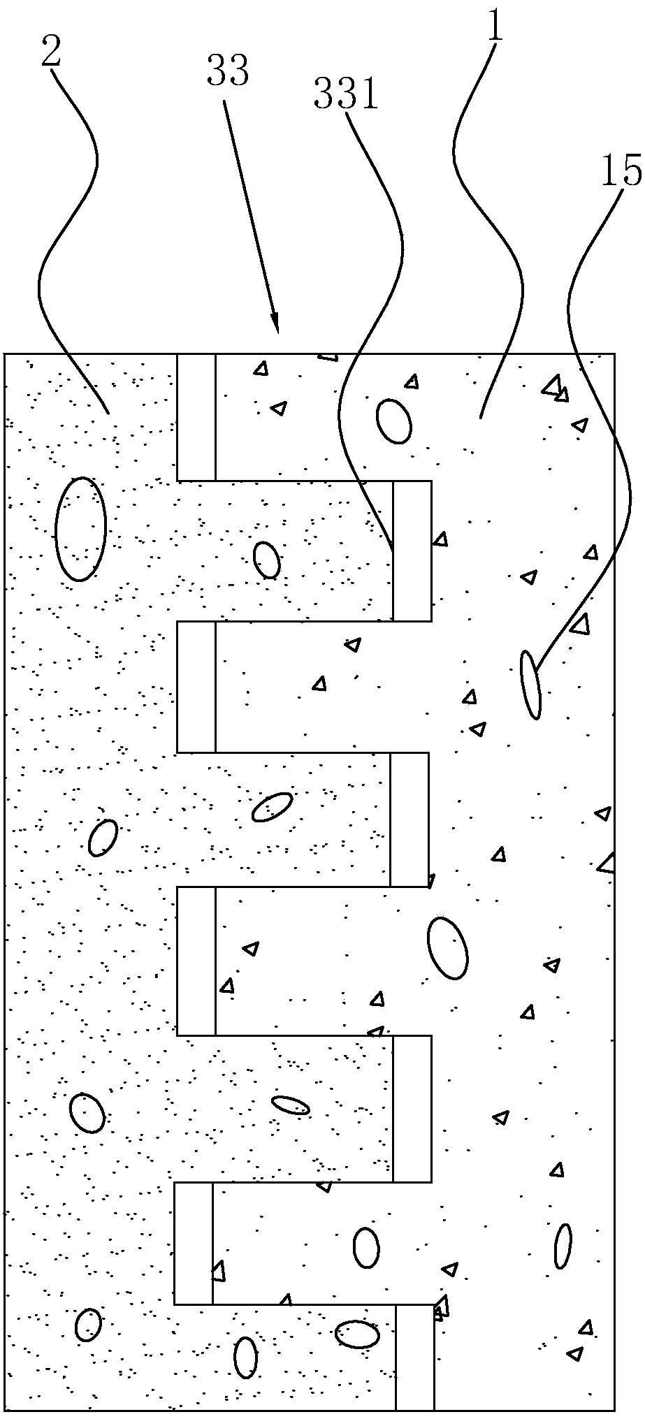
[0037] Embodiment: A basement connecting part anti-crack structure, including an inner connecting part 1 and an outer connecting part 2, the inner connecting part 1 is integrally connected with the basement, the outer connecting part 2 is directly connected to other buildings outside the basement, and the inner connecting part A deformation buffer seam is left between 1 and the outer connecting part 2. refer to Figure 1-3 , the deformation buffer seam is provided for one week, including a bottom horizontal seam 31, a top horizontal seam 32 and two side vertical seams 33.

[0038] Such as figure 1 As shown, the bottom horizontal seam 31 is provided with a subsidence buffer zone, and the subsidence buffer zone is provided with multiple groups of reinforcement belts 5 according to its width, and each two reinforcement belts 5 arranged in a staggered manner form a group, and the reinforcement belts 5 are formed by two The connecting section 1 and the outer connecting section 2 ...


PUM


Abstract

The invention discloses a basement connection portion crack preventing structure which comprises an internal connecting part, an external connecting part and a deformation buffer slit. A settlement buffer zone is arranged at the bottom of the deformation buffer slit, the internal connecting part and the external connecting part at two sides of the deformation buffer slit are in snap joint, and ananti-crack waterproof assembly is arranged at the top of the deformation buffer slit. The settlement buffer zone comprises reinforcing belts; each reinforcing belt comprises a connecting section and an anti-shear section, since the connecting section of the reinforcing belt has difference in vertical height, the anti-shear section is oblique; the connecting sections refer to a rigid connectors buried in the internal connecting part and the external connecting part and the anti-shear sections refer to elastic connectors. According to the arrangement, the anti-shear sections refer to elastic parts having a certain deformability and can reduce the probability of cracking of the settlement buffer slit; besides, the snap joint can increase adhesion stress between the two parts so that settlement of the basement connection portion can be synchronous to the utmost extent; the anti-crack waterproof assembly arranged at the top can reduce crack and water seepage further; therefore, the whole basement connection portion has excellent anti-crack and waterproof effect.

Description

technical field [0001] The invention relates to the field of building construction, in particular to an anti-crack structure for a basement connecting part. Background technique [0002] With the development of cities, the requirements for urban buildings are becoming more and more diverse. The most obvious one is that urban buildings at this stage are basically developing towards high-rise or super-high-rise buildings. pay more attention to. In order to further adapt to the building stability of high-rise and ultra-high-rise buildings, most urban buildings are designed with basement structures, which can not only further increase the land utilization rate, but also provide a good and stable stress-bearing foundation for the superstructure. [0003] And because the basement is under the soil layer for a long time, the waterproof requirements for the basement are correspondingly higher. For example, the Chinese patent document with the application publication number CN10249...

Claims


Application Information

Patent Timeline
Patent Type & Authority Applications(China)
IPC IPC(8): E02D31/02E02D31/04E02D29/16
CPCE02D29/16E02D31/02E02D31/04
Inventor 赵建营李运双
Owner 浙江联建工程设计有限公司
Why Eureka
Try Eureka