Non-rivet riveting device and method for carbon fiber composite material and aluminum alloy

A rivetless riveting and composite material technology, which is applied in the field of composite material riveting, can solve the problems of matrix cracking, fiber breakage, and low joint performance, and achieve the effects of improving tensile strength, reducing damage, and reducing quality

Active Publication Date: 2018-08-10
JILIN UNIV
View PDF7 Cites 7 Cited by
  • Summary
  • Abstract
  • Description
  • Claims
  • Application Information

AI Technical Summary

Problems solved by technology

[0006] The purpose of the present invention is to provide a rivetless riveting device and method for carbon fiber composite materials and aluminum alloys, and solve the technical problems existing in the prior art that are prone to fiber breakage, matrix cracking, interface degumming and delamination, and low joint performance

Method used


Image

  • Non-rivet riveting device and method for carbon fiber composite material and aluminum alloy
  • Non-rivet riveting device and method for carbon fiber composite material and aluminum alloy
  • Non-rivet riveting device and method for carbon fiber composite material and aluminum alloy

Examples


Embodiment 1

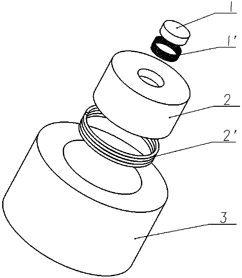
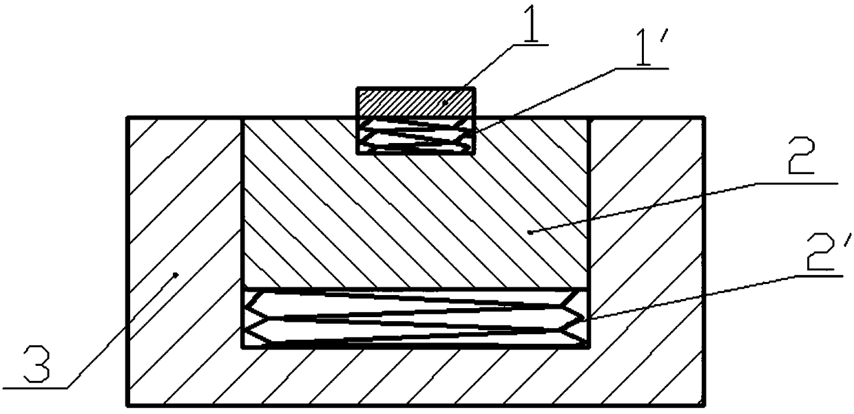
[0057] See attached Figure 1-9 The rivetless riveting device between carbon fiber composite material and aluminum alloy of the present invention includes a blank holder 6, a punch 7 and a die; the die includes a spring pad I1, a spring pad II2, a spring I1', a spring II2' and a lower mod 3;

[0058] A through hole for positioning the punch 7 is arranged at the structural center of the blank holder 6, and the punch 7 moves up and down in the through hole of the blank holder 6 during the riveting process;

[0059] The punch 7 is an integrated structure, including a needle body and a needle head; the needle body is cylindrical, the needle head is a circular truncated shape, and the side of the needle head circular pedestal has a small inclination angle, all inclined towards the center line of the needle body; The arc surface transition is adopted between the needle body and the needle head, and the arc surface transition is also adopted between the top surface and the side of t...

Embodiment 2

[0103] The method for realizing the rivetless riveting device between the carbon fiber composite material and the aluminum alloy by applying the above-mentioned device includes the following steps:

[0104] Step 1: cutting a through hole with a diameter of 8 mm in the center of the carbon fiber composite material plate 4 by a numerical control CNC machine tool;

[0105]Step 2: Place the carbon fiber composite material plate 4 and the aluminum alloy 5 with a through hole of 8 mm in step 1 on the die in sequence from bottom to top, punch 7, blank holder 6, carbon fiber composite material plate through hole and The die is placed concentrically, and the blank holder 6 is driven to move down until the carbon fiber composite material plate 4 and the aluminum alloy plate 5 are pressed;

[0106] Step 3: Put the punch 7 into the fixture of the riveting machine and lock it, then start the riveting machine, send the punch 7 into the center positioning through hole of the blank holder 6, ...


PUM

PropertyMeasurementUnit
diameteraaaaaaaaaa
lengthaaaaaaaaaa
diameteraaaaaaaaaa

Abstract

The invention discloses a non-rivet riveting device and method for a carbon fiber composite material and an aluminum alloy and belongs to the technical field of composite material riveting. The technical problems that in the prior art, fiber breakage, matrix cracking and interface degumming and layering are likely to occur and the joint performance is low are solved. The device comprises a blank holder, a punch and a concave mold. The concave mold comprises a first spring cushion block, a second spring cushion block, a first spring, a second spring and a lower mold body. The non-rivet rivetingprocess of the carbon fiber composite material and the aluminum alloy is achieved through the device. By means of the process, an aluminum alloy plate forms a self-locking structure at a through holeof a carbon fiber composite material plate, the anti-tension, anti-shear and anti-fatigue properties of a joint are improved, riveting elements like rivets are not needed, and the mass is reduced.

Description

technical field [0001] The invention belongs to the technical field of riveting of composite materials, and in particular relates to a rivetless riveting device and method for carbon fiber composite materials and aluminum alloys. Background technique [0002] Safe, energy-saving and environment-friendly automobiles have become the mainstream of automobile development in the 21st century. Automobile lightweight is undoubtedly the best way, and one of the mainstream materials for automobile lightweight is lightweight materials such as aluminum alloy and composite materials for automobiles, especially Composite materials are the preferred materials for new energy vehicles. Because of their low material density, high specific strength, and high specific stiffness, they are very suitable for the research and development needs of new energy vehicles. [0003] At the same time, the non-destructive connection of composite materials and metal materials is an important assembly proble...

Claims


Application Information

Patent Timeline
Patent Type & Authority Applications(China)
IPC IPC(8): B21D39/03
CPCB21D39/031Y02T50/40
Inventor 庄蔚敏武世杰吴迪敖文宏施宏达王鹏跃
Owner JILIN UNIV
Why Eureka
Try Eureka