Laser Selective Melting Scanning Method

A technology of laser selective melting and scanning method, applied in the field of additive manufacturing, can solve the problems of rough surface of molded parts, no good progress, poor surface quality, etc., to achieve excellent surface quality, reduce step effect, and high molding efficiency. Effect

Active Publication Date: 2019-01-29
OPTIMAL MATERIAL TECH CO LTD
View PDF7 Cites 0 Cited by
  • Summary
  • Abstract
  • Description
  • Claims
  • Application Information

AI Technical Summary

Problems solved by technology

However, the aerospace and biomedical fields, especially the dental field, have very high requirements on the surface quality of the parts. The surface quality of the parts formed by the SLM process cannot be compared with the cutting parts. The unreasonable setting of the process parameters leads to the surface quality of the molded parts. Rough, follow-up processing is cumbersome
Especially for the overhanging surface, its surface quality is relatively poor. Although relevant technical personnel have been working hard to explore improvement methods for this problem, they have not made good progress.

Method used


Image

  • Laser Selective Melting Scanning Method
  • Laser Selective Melting Scanning Method
  • Laser Selective Melting Scanning Method

Examples


Embodiment Construction

[0038] The present invention is further described below.

[0039] Laser selective melting molding process usually includes the following steps:

[0040] Data processing: process the designed molded parts layer by layer,

[0041] Additive processing: use the following laser selective melting scanning method to perform laser scanning processing on each layer after layering processing.

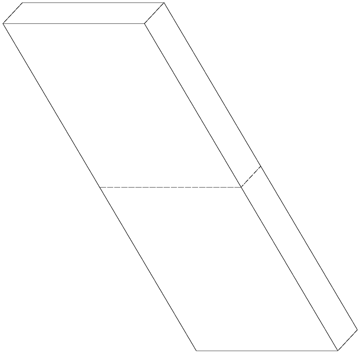
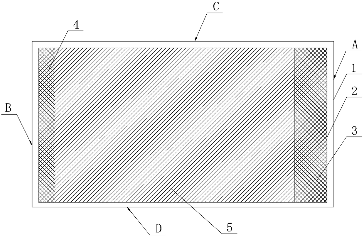
[0042] The present invention improves the laser selective melting scanning method, and its level scanning includes the following area scanning:

[0043] Contour scan: scan along the outer contour of the layer;

[0044] Internal fill line scan: perform fill scan in the internal area of ​​the layer;

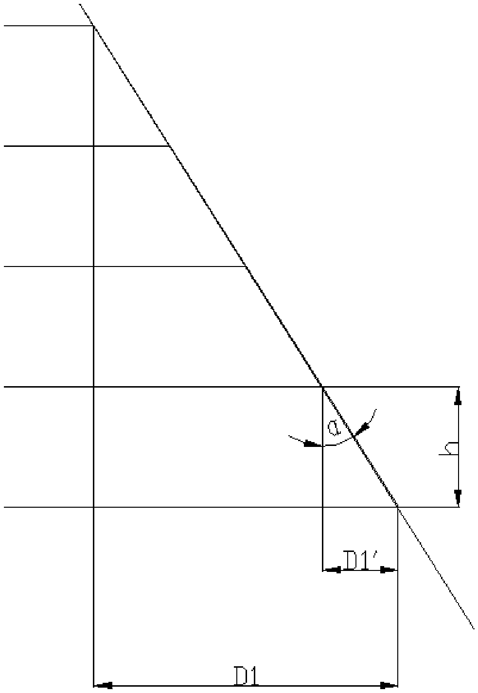
[0045] Upper skin scanning: scan the upper skin area inside the contour line, the upper skin area is located on the side of the layer close to the upper surface of the molding, and the upper skin area is located between the outer contour line and the inner area, the upper skin area area width D 1...


PUM

PropertyMeasurementUnit
diameteraaaaaaaaaa

Abstract

The invention relates to the field of additive manufacturing, and discloses a laser selective melting scanning method. In the laser selective melting scanning method, the layer scan includes the following area scans: contour scan: scan along the outer contour line of the layer; internal filling line scan: perform filling scan in the inner area of ​​the layer; upper epidermis scan: scan inside the contour line The upper epidermis area is scanned, and the width D1 of the upper epidermis area satisfies the following relationship: D1=ah·tanα, the lower epidermis scan: the lower epidermis area inside the contour line is scanned, and the width D1 of the upper epidermis area satisfies the following Relational formula: D2=bh·tanβ. Using this method, the surface of the formed part has obvious metallic luster, and the surface quality is better; the combination of powder metallurgy is sufficient, and the performance of the formed part is better; the scanning speed can also be improved, and the forming efficiency is higher, especially for the overhanging surface of the formed part. , can reduce the step effect of its surface, thereby improving its molding quality.

Description

technical field [0001] The invention relates to the field of additive manufacturing, in particular to a laser selective melting scanning method. Background technique [0002] Additive manufacturing, also known as 3D printing, can form complex-shaped parts with high forming precision and save materials. It has the cost advantage of forming complex objects, can provide personalized customization services, simplifies the production process, and is energy-saving and environmentally friendly during the production process. At present, it has been widely used in aerospace, biomedical, military, construction, automobile, jewelry, mold and other industries. [0003] Laser selective melting (SLM) is a kind of 3D printing technology, especially for personalized customization, integrated molding of complex structures and other applications, it can provide an ideal solution, so it has a wide range of applications in aerospace and biomedical fields prospect. However, the aerospace and b...

Claims


Application Information

Patent Timeline
Patent Type & Authority Patents(China)
IPC IPC(8): B22F3/105B33Y30/00
CPCB33Y30/00B22F10/00B22F10/28B22F10/366Y02P10/25
Inventor 邹善方刘睿诚吴利苹张志霄姚圳珠曾益伟
Owner OPTIMAL MATERIAL TECH CO LTD
Why Eureka
Try Eureka