
Ultrasonic machining tool with three groups of ultrasonic vibrators formed into conical structure and controlling method

An ultrasonic vibrator and ultrasonic machining technology, which is used in metal processing equipment, grinding machine parts, grinding automatic control devices, etc., can solve the problems of uneven processing residue and low processing efficiency.

Active Publication Date: 2018-08-10
JILIN UNIV
View PDF10 Cites 3 Cited by
  • Summary
  • Abstract
  • Description
  • Claims
  • Application Information

AI Technical Summary

Problems solved by technology

[0004] This patent aims to solve the defects in the processing mechanism of two-dimensional ultrasonic grinding and polishing, as well as the uneven processing residue caused by the traditional processing path planning method, and the planning of the micro-movement trajectory of the tool grinding and polishing head is limited, which makes the processing efficiency low. The problem is to propose an ultrasonic machining machine tool with three sets of ultrasonic vibrators forming a cone structure and its control method. Through the inverse solution algorithm of the micro-movement trajectory, the three ultrasonic vibrators can drive the grinding and polishing head to output the predetermined micro-movement trajectory required for processing. , the predetermined micro-movement track can be preset according to the requirements of the micro-geometric shape and physical and mechanical properties of the processed surface, and combined with the use of the equal tangential length increment method to plan the macro-processing track, the residual amount can be uniform and the machining accuracy can be improved. and the purpose of workpiece surface quality

Method used


Image

  • Ultrasonic machining tool with three groups of ultrasonic vibrators formed into conical structure and controlling method
  • Ultrasonic machining tool with three groups of ultrasonic vibrators formed into conical structure and controlling method
  • Ultrasonic machining tool with three groups of ultrasonic vibrators formed into conical structure and controlling method

Examples


Embodiment Construction

[0074] The implementation and working process of the present invention will be further described below in conjunction with the embodiments shown in the accompanying drawings.

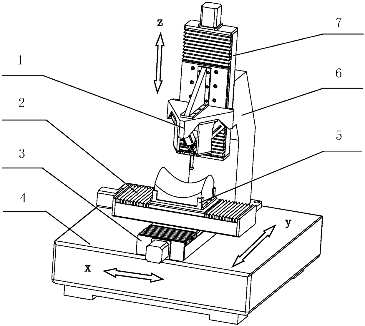
[0075] figure 1 It is a schematic diagram of the overall structure of the present invention, an ultrasonic machining machine tool with three groups of ultrasonic vibrators in a cone structure, including an ultrasonic tool system 1, a transverse guide rail 2, a longitudinal guide rail 3, a machine tool base 4, a workpiece fixture 5, and a vertical guide rail mounting arm 6 and the vertical guide rail 7, the longitudinal guide rail 3 is longitudinally fixedly installed in the middle position on the upper side of the machine base 4, the transverse guide rail 2 is laterally fixedly installed on the slide plate of the longitudinal guide rail 3, and the workpiece fixture 5 is fixedly installed on the slide plate of the transverse guide rail 2 Above, the vertical guide rail installation arm 6 is fixedly installe...


PUM


Abstract

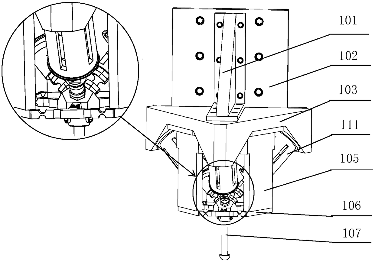
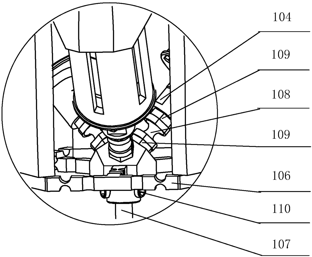
The invention discloses an ultrasonic machining tool with three groups of ultrasonic vibrators formed into a conical structure and a controlling method. A hinge base is mounted on the lower side of atriangular fixed plate; a flexible hinge is mounted at the lower end of the hinge base; three ultrasonic vibrator fixed sleeves are respectively fixed on three inclined mounting bases positioned on the lower side of the triangular fixed plate; three ultrasonic vibrators are respectively sleeved in the ultrasonic vibrator fixed sleeves; one corresponding end of each of three small hinges is respectively connected with the corresponding output end of the corresponding ultrasonic vibrator through double-end bolts while the other end of each of the three small hinges is connected with a corresponding mounting platform positioned in the middle of the upper side of the flexible hinge; and a cutter is mounted in a cutter mounting hole formed in the middle of the lower side of the flexible hinge.The three ultrasonic vibrators of a tool system of the ultrasonic machining tool disclosed by the invention are formed into the conical structure, and an inverse solution thinking way of a micro-motion track of a sphere point of a grinding and polishing head and a macro-control method using isotropic tangential length incremental method as a main content, the aims that the machining precision of an ultrasonic grinding and polishing machine tool is improved and the surface quality of machined parts is improved are fulfilled.

Description

technical field [0001] The invention relates to an ultrasonic processing machine tool with three sets of ultrasonic vibrators forming a cone structure, belonging to the technical field of ultrasonic processing. Background technique [0002] Ultrasonic grinding and polishing is a special processing method based on the ultrasonic vibration of the grinding and polishing head. Ultrasonic grinding and polishing can process hardened steel parts and superhard parts that are difficult to process by traditional mechanical processing methods, and can obtain high Machining accuracy and surface quality have become an important processing method in the field of ultra-precision machining, so it is widely used in cutting, grinding and polishing of various difficult-to-machine materials in aviation, aerospace, military and other fields. [0003] Most of the existing ultrasonic grinding and polishing machine tools are two-dimensional. For example, in the patent of publication number CN106736...

Claims


Application Information

Patent Timeline
IPC IPC(8): B24B1/04B24B41/06B24B47/20B24B51/00
CPCB24B1/04B24B41/06B24B47/20B24B51/00Y02P90/02
Inventor 冀世军张超赵继代汉达贺秋伟杨记龙
Owner JILIN UNIV
Learn More