
Composite 3D printing system and method recognizing defected feature in non-contact manner

A non-contact identification and 3D printing technology, applied in manufacturing auxiliary devices, processing drive devices, processing data acquisition/processing, etc., can solve the wider application limitations of 3D printing technology, the large area of ​​printer hardware, and the limitation of printing range, etc. problem, to achieve the effect of compact structure, light weight, and reduce the restrictions on the use of the site

Active Publication Date: 2018-08-10
XI AN JIAOTONG UNIV
View PDF2 Cites 12 Cited by
  • Summary
  • Abstract
  • Description
  • Claims
  • Application Information

AI Technical Summary

Problems solved by technology

The print head is installed on the motion axis, and the print head can only move linearly on the X, Y, and Z coordinate axes. With this structure, the printer hardware occupies a large area, and the printing range is limited by the motion axis. Print in the space surrounded by the limit values ​​of the coordinate axes. During the printing process, the position of the printed object is strictly limited and cannot be moved arbitrarily.
The above shortcomings greatly limit the wider application of 3D printing technology in the field of restoration and manufacturing

Method used


Image

  • Composite 3D printing system and method recognizing defected feature in non-contact manner
  • Composite 3D printing system and method recognizing defected feature in non-contact manner
  • Composite 3D printing system and method recognizing defected feature in non-contact manner

Examples


Embodiment example

[0054] Rat skin surface defect repair:

[0055] According to the principle of a composite 3D printing system and method for non-contact recognition of defect morphology of the present invention as mentioned above, the following specific implementation cases are adopted:

[0056] In the image recognition system, the light source is a commercial projector, and the digital camera is a CCD industrial camera. Among them, the resolution of the projector is 720P, and the pixel of the CCD industrial camera is 1280*960. Under the installation distance of 50cm to 100cm, the image recognition range is 20cm (length) * 20cm (width) * 2cm (height). The measurement time is within 30 seconds.

[0057] The installation height of the CCD industrial camera was adjusted several times, and the frame height was selected as 60cm by comparing the imaging effect. Use the national standard 40 series GY-4040 profiles, GY-4040 heavy-duty corner codes, M6-L12 bolts and GY-08-M6 square nuts to build a 50...


PUM


Abstract

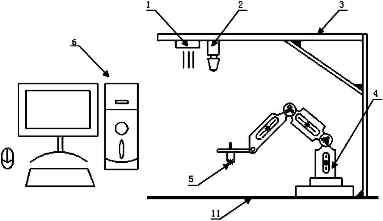
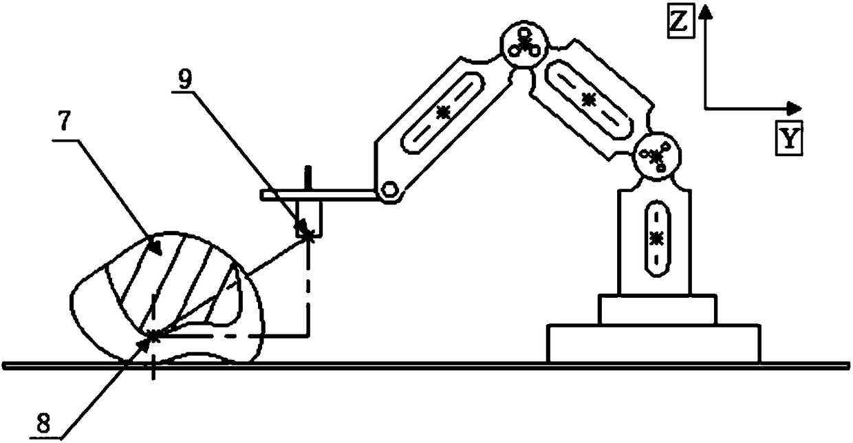
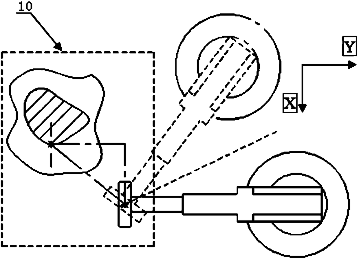
The invention discloses a composite 3D printing system and method recognizing the defected feature in a non-contact manner. The system is composed of three parts including an image recognizing system,a motion control system and a data processing system. The image recognizing system comprises a light source and a digital camera, defected part images are collected in real time, and the current position of a printing head is captured. The motion control system comprises a multi-freedom-degree mechanical arm and the printing head. The mechanical arm can be arranged at any position where the printing head can be recognized, and the printing head is arranged at the tail end of the multi-freedom-degree mechanical arm. The data processing system achieves real-time data conversion between the image recognizing system and the motion control system, automatic printing head alignment, path feature point extraction and printing control. The system can rapidly recognize the defected parts differentin feature, the printing process is synchronously controlled, recognizing and printing are conducted at the same time, and the composite 3D printing system and method can be applied to the fields including but not limited to real-time defected structure repairing and mechanical component machining.

Description

technical field [0001] The invention belongs to the technical field of additive manufacturing in mechanical manufacturing, and in particular relates to a composite 3D printing system and method for non-contact recognition of defect morphology. Background technique [0002] In recent years, 3D printing technology has developed rapidly, playing an increasingly important role in the fields of automobiles, aerospace, medicine and biological research, and a wide variety of 3D printers have emerged. [0003] Taking the application in the existing biomedical field as an example, in surgical repair, the existing 3D printing technology is mainly used for the production of customized surgical models and personalized implants. After extraction, a complete three-dimensional model is established in the computer, and then it is processed layer by layer, and then the bioprinter is controlled to print layer by layer. The obvious disadvantage of this process is that the operation cycle is lo...

Claims


Application Information

Patent Timeline
IPC IPC(8): B29C64/20B29C64/227B29C64/386B33Y10/00B33Y30/00B33Y50/00
CPCB29C64/20B29C64/227B29C64/386B33Y10/00B33Y30/00B33Y50/00
Inventor 连芩李涤尘顾恒李晓何晓宁焦天
Owner XI AN JIAOTONG UNIV
Learn More