Device for rapidly measuring surface flatness of object

A technology of object surface and measuring device, applied in the fields of production, inspection, machinery, testing, industry and optics, which can solve the problems of over-specialized theoretical foundation, influence of measurement accuracy, and lack of suppression means.

Inactive Publication Date: 2018-08-10
仲东明
View PDF0 Cites 6 Cited by
  • Summary
  • Abstract
  • Description
  • Claims
  • Application Information

AI Technical Summary

Problems solved by technology

[0011] The above methods are mature and can achieve precise measurement, but the theoretical basis is too professional and requires professionals to operate and

Method used


Image

  • Device for rapidly measuring surface flatness of object
  • Device for rapidly measuring surface flatness of object
  • Device for rapidly measuring surface flatness of object

Examples


specific Embodiment 2

[0078] This embodiment is an embodiment of the device for quickly measuring the surface flatness of an object of the present invention.

[0079] The device for quickly measuring the flatness of the object surface in this embodiment is further defined on the basis of the first embodiment: the exposure time of the image sensor 1-9 is the same as the stagnation time of the stage 1-3.

specific Embodiment 3

[0080] This embodiment is an embodiment of the method for quickly measuring the surface flatness of an object according to the present invention.

[0081] The method for quickly measuring the flatness of the surface of the object in this embodiment of the present invention is implemented on the device for quickly measuring the flatness of the surface of the object described in the first embodiment or the second embodiment.

[0082] The method for quickly measuring the flatness of the object surface of the present invention comprises the following steps:

[0083] Step a. Adjust the measured object 1-6 so that a certain position on the upper surface of the measured object 1-6 is located at the focus position of the objective lens 1-4, and the limit protrusion 2-9 is required to be located at the moving block 2 The lowest point in the inferior arc slot in -3, the limit protrusion 2-9 is located at the lowest point of its motion track;

[0084] Step b, setting the imaging time t ...

specific Embodiment 4

[0097] This embodiment is an embodiment of the device for quickly measuring the surface flatness of an object of the present invention.

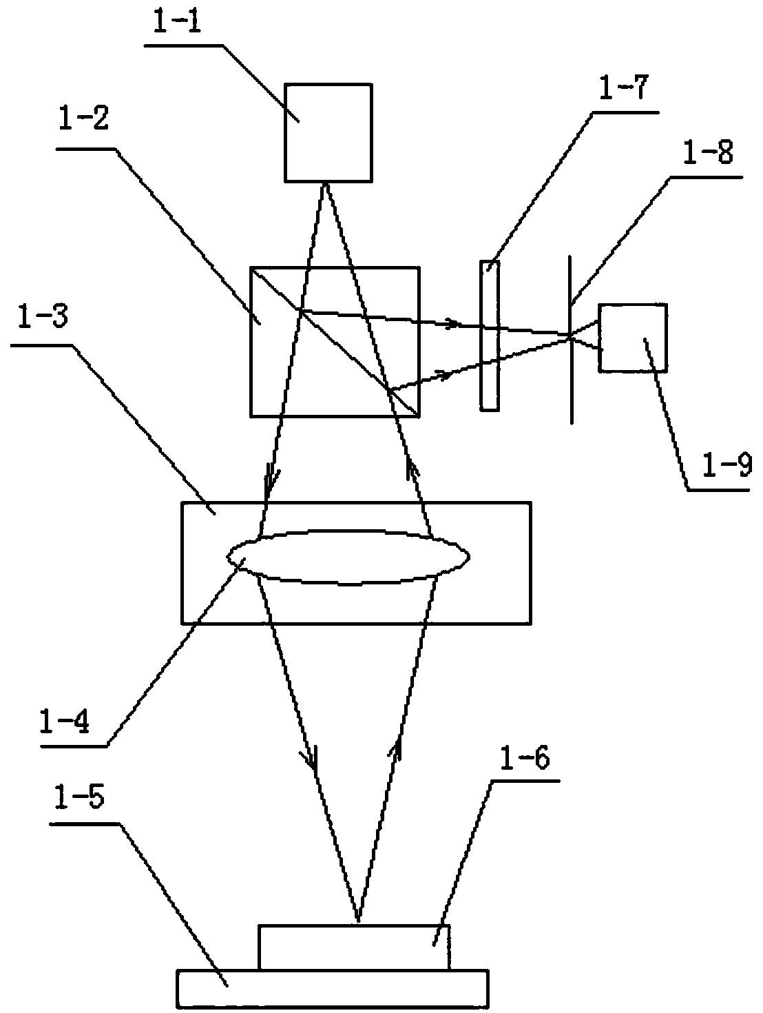
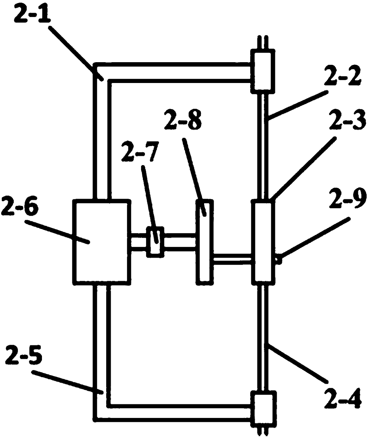
[0098] A rapid measuring device for surface flatness of an object, which is composed of an illumination imaging module and a motion mechanism; wherein, the schematic diagram of the illumination imaging module is as follows figure 1 As shown, the structure diagram of the motion mechanism is shown in figure 2 shown.

[0099] The illumination imaging module is composed of an illumination system and an imaging system; in the illumination system, a laser 1-1, a beam splitter 1-2, an objective lens 1-4, and a measured object 1-6 are sequentially arranged along the light propagation direction; The objective lens 1-4 is carried by the stage 1-3 and moves along the direction of the optical axis; the measured object 1-6 is carried by the two-dimensional translation stage 1-5 and moves two-dimensionally in the plane perpendicular to the optical axis;...


PUM


Abstract

A device for rapidly measuring the surface flatness of an object of the invention belongs to the technical field of optical inspection and testing of industrial production machinery. The device is composed of an illumination imaging module and a motion mechanism; the illumination imaging module is composed of an illumination system and an imaging system; in the illumination system, a laser, a beamsplitter, an objective lens and a measured object are sequentially arranged along the light propagation direction; in the imaging system, an object to be tested, an objective lens, a beam splitter, an attenuator, a pinhole and an image sensor are sequentially arranged along the light propagation direction; the moving mechanism consists of an upper fixed end, an upper rod, a moving block, a lowerrod, a lower fixed end, a motor, a coupling, a T type turntable and a limit protrusion; when the motion block is in motion, a beam emitted by the laser is defocused to the surface of the object to betested, and a beam reflected by the object to be tested is defocused onto the pinhole. The device not only can qualitatively detect the surface flatness of the object, but also is simple in operationprocess and easy in operation method, and can filter or monitor the noise, and the detection result is accurate.

Description

technical field [0001] The device for quickly measuring the flatness of an object surface according to the invention belongs to the technical fields of industry, production, machinery, optics, detection, testing and the like. Background technique [0002] Flatness measurement refers to the variation of the measured actual surface to its ideal plane. [0003] The flatness error is to compare the measured actual surface with the ideal plane, and the line value distance between the two is the flatness error value; or by measuring the relative height difference of several points on the actual surface, and then converting it to the line value Flatness error value. [0004] The common methods of flatness error measurement are as follows: [0005] 1. Flat crystal interferometry: use the working surface of the optical flat crystal to reflect the ideal plane, and directly determine the flatness error value of the measured surface by the curvature of the interference fringes. [00...

Claims


Application Information

Patent Timeline
IPC IPC(8): G01B11/30
CPCG01B11/30
Inventor 仲东明
Owner 仲东明
Why Eureka
Try Eureka