
Electric energy gauge seal testing machine

A technology of electric energy meters and testing machines, which is applied in the direction of measuring electric variables, measuring devices, instruments, etc., can solve the problems of no common equipment, etc., and achieve the effects of stable operation, safe testing process, and accurate data

Active Publication Date: 2018-08-10
国网山西省电力公司计量中心
View PDF4 Cites 2 Cited by
  • Summary
  • Abstract
  • Description
  • Claims
  • Application Information

AI Technical Summary

Problems solved by technology

In order to standardize the use and management of electric energy metering seals by power companies, in 2013, the State Grid Corporation of China issued the enterprise standard Q / GDW 11009-2013 Technical Specifications for Electric Energy Metering Seals, which systematically classified the electric energy metering seals for the first time, and proposed The requirements of 9 test items are specified, namely, structure and dimension inspection, appearance inspection, barcode quality inspection, strength test, destruction test, sealing force and unsealing force test, safety test, radio frequency technology test, and climate impact test. Among them, structure and Dimensional inspection, appearance inspection, barcode quality inspection, safety test, radio frequency technology test, etc., can be completed either by intuitive visual inspection, or by mature equipment such as calipers, barcode detectors, and spectrometers, while strength tests, destruction tests, sealing force The three items of the unsealing force test and the unsealing force test are newly proposed concepts, and there is currently no general-purpose equipment that can be used

Method used


Image

  • Electric energy gauge seal testing machine
  • Electric energy gauge seal testing machine
  • Electric energy gauge seal testing machine

Examples


Embodiment Construction

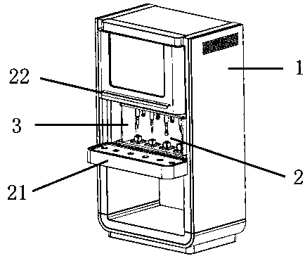
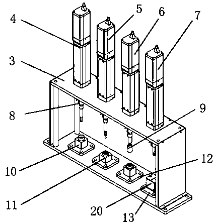
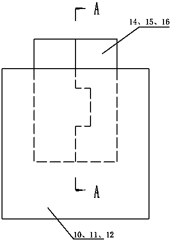
[0015]The electric energy meter seal testing machine includes an upper PC and a lower testing cabinet. The lower testing cabinet includes a cabinet 1. The upper part of the cabinet 1 is an industrial computer connected to the upper PC. The industrial computer includes an integrated The electric control panel, PLC, air switch and relay of the electric control module are installed; the front of the middle part of the cabinet body 1 has a work area 2, and the work area 2 is vertically provided with a test installation frame 3, and the upper part of the test installation frame 3 The first servo electric cylinder 4, the second servo electric cylinder 5, the third servo electric cylinder 6, and the fourth servo electric cylinder 7 that are connected to the industrial computer are vertically pierced. The first servo electric cylinder 4, The ends of the second servo electric cylinder 5, the third servo electric cylinder 6, and the fourth servo electric cylinder 7 are respectively provi...


PUM

PropertyMeasurementUnit
diameteraaaaaaaaaa
diameteraaaaaaaaaa

Abstract

The invention relates to an electric energy gauge detection device and in particular relates to an electric energy gauge seal testing machine, aiming at solving the problems that testing equipment fortesting strength, a destructive force, a sealing force and an unsealing force of a newly developed electric energy gauge seal is lacked at present. The electric energy gauge seal testing machine is characterized by comprising an upper PC (Personal Computer) and a lower testing cabinet machine, wherein an industrial control computer is arranged at the upper part of a cabinet body; a mounting frameis arranged in a middle working region; four servo electric cylinders are arranged on the mounting frame and clamps are correspondingly mounted. The electric energy gauge seal testing machine is usedfor testing the sealing force, the unsealing force, the destructive force and the reliability of buckle type and threading type seals respectively. The electric energy gauge seal testing machine hasthe advantages that a test is accurately simulated; a whole testing process is safe and reliable and data is accurate and can be displayed through a graph; the device has the advantages of stability in operation and high testing efficiency and provides powerful guarantees for quality detection of seal products.

Description

technical field [0001] The invention relates to an electric energy meter detection device, in particular to an electric energy meter seal tester. Background technique [0002] At present, a large number of old-fashioned lead seals are still used on measuring instruments. This kind of lead seal is easy to imitate and easy to open. Under normal conditions, it is difficult to distinguish its authenticity and whether it has been illegally altered by others during use; The jaws of the pliers are loaded with extremely limited information, and the power sector cannot manage them as assets. Lead seals are already in a relatively backward state in terms of power consumption management and anti-theft technology; heavy metal pollution caused by old-fashioned lead seals , in today's ever-increasing awareness of environmental protection, it is also a problem that cannot be ignored; at the same time, as the last link of the automatic assembly line verification system of smart electric ene...

Claims


Application Information

Patent Timeline
Patent Type & Authority Applications(China)
IPC IPC(8): G01N3/02G01N3/04G01R35/04
CPCG01N3/02G01N3/04G01R35/04
Inventor 靳海岗任峰赵轶彦陈安琪李晓斌曹媛媛王刚王晖南马元培张振国
Owner 国网山西省电力公司计量中心
Learn More