Method for continuously monitoring and controlling cased well fracturing based on well-ground potential imaging

A monitoring and control, cased well technology, applied in the field of geological exploration, can solve the problems of the inability to know the dynamic extension of the fracturing fluid in the dynamic advancing direction of the fracturing fracture, the small number of electrodes in the observation system, and the low azimuth resolution, etc., so as to improve the accuracy. , low usage, the effect of increasing the amount of information

Active Publication Date: 2018-08-10
东方华隆(北京)石油技术有限公司
View PDF8 Cites 2 Cited by
  • Summary
  • Abstract
  • Description
  • Claims
  • Application Information

AI Technical Summary

Problems solved by technology

This method has the following disadvantages: first, the number of electrodes in the observation system is relatively small, and the azimuth resolution is not high; In the post-fracture state, it is impossible to know the dynamic propulsion direction of the fracturing fluid and the dynamic extension of the fracturing fracture during the fracturing process; third, it is impossible to control the entire fracturing process according to the real-time extension of the fracturing fracture

Method used


Image

  • Method for continuously monitoring and controlling cased well fracturing based on well-ground potential imaging
  • Method for continuously monitoring and controlling cased well fracturing based on well-ground potential imaging
  • Method for continuously monitoring and controlling cased well fracturing based on well-ground potential imaging

Examples


Embodiment 1

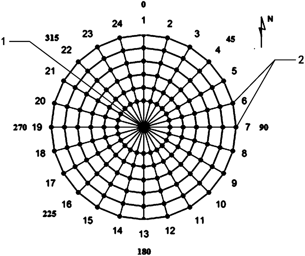
[0025] This example presents a method of measuring point layout for a cased well fracturing continuous monitoring and control method based on well-ground potential imaging, as shown in figure 1 As shown, with the measured cased well 1 as the center of the circle, radial measuring points 2 are arranged circularly on the ground. The arrangement of the measuring points 2 is 6 ring measuring points, the radius of each ring is 50 meters, 100 meters, 150 meters, 200 meters, 250 meters, 300 meters, and the angle between two adjacent measuring points in each ring is 15 degrees, 24 measuring points are arranged in each ring. The casing of the measured cased well 1 is connected to a power supply, and the measuring point is provided with a potential acquisition device for measuring the potential of the measuring point, and the potential data of the measuring point is sent to the data processing and analysis device at the back end by wired or wireless means .

Embodiment 2

[0027] This embodiment provides a method for continuous monitoring and control of cased well fracturing based on well-ground potential imaging, including the following steps:

[0028] 1. With the measured cased well as the center of the circle, radial measuring points are arranged circularly on the ground. Refer to Embodiment 1 for the specific arrangement.

[0029] 2. Supply current downhole through the casing, start the fracturing process, and continuously measure and collect the data of the supplied current and the potential data of the measuring point. Specifically, the measurement point data can be collected at constant time intervals (for example, the whole process of fracturing is expected to be 1 to 2 hours, and the time interval is set to 1 to 10 minutes), and the time of said data collection should cover before starting fracturing and before injection. The whole process of fracturing is monitored and displayed in real time during the whole process of fracturing, suc...

Embodiment 3

[0035] This example shows the effect of fracturing the 3044.8-3008.8m well section of Well S141 using the method described in Example 2. During construction, the data is collected at intervals of 5 minutes, and the results are as follows:

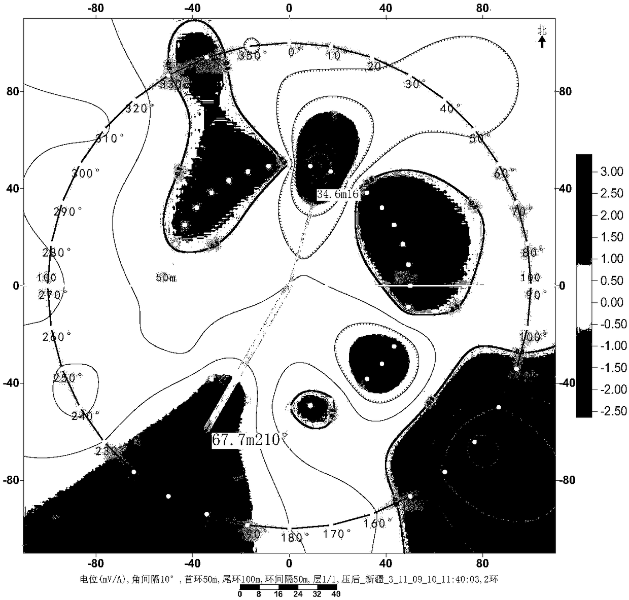
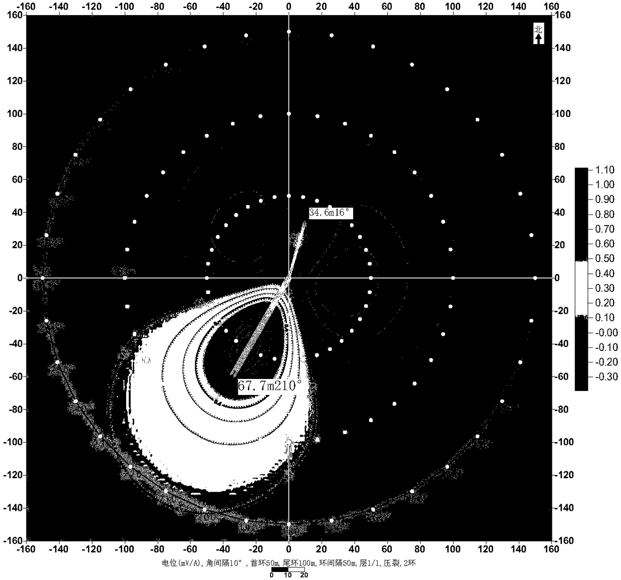
[0036] Figures 2 to 4 They are the potential measurement results of different rings before fracturing, after fracturing, and during fracturing (when sand-carrying fluid is injected). in, figure 2 and image 3 The potential imaging diagrams of the six rings before and after fracturing are shown respectively. It can be seen that the images before and after fracturing have obvious changes. There are fractures developed in one direction or abnormal development of permeable zone, and the imaging map after fracturing indicates that south-south west is the main fracturing direction. Figure 4 It is the section view of the first ring and the second ring (ie, 50-meter ring and 100-meter ring) from the inside to the outside during fracturing (w...


PUM

PropertyMeasurementUnit
lengthaaaaaaaaaa

Abstract

The invention relates to a method for continuously monitoring and controlling cased well fracturing based on well-ground potential imaging. The method comprises the following steps: (1) (1) measuringpoints radially inside and outside the ground ring arrangement; (2) supplying current to downhole by means of a casing, starting a fracturing process, and continuously measuring and collecting data ofsupplied current and potential data of the measured points; (3) carrying out standardization on the data of supplied current and performing normalization on the potential data of the measured points;(4) drawing and a potential ring profile map and a plane contour map, and displaying same in real time; (5) controlling the fracturing process. After the method is adopted, firstly, the accuracy of the measured data is improved by increasing the ring values and number of the measured points; secondly, by increasing the times of measurement in the fracturing process, the propulsion direction of fracturing fluid and the extension status of fractured cracks are displayed in real time, so that continuous visual monitoring of the fracturing process is realized; thirdly, the fracturing process canbe controlled according to the real-time display of the extension status of the fractured cracks, and the consumption of the fracturing fluid is minimized under the premise of guaranteeing the fracturing effect.

Description

technical field [0001] The invention belongs to the technical field of geological exploration, and relates to a method for detecting and monitoring oil well fracturing by using an electric field, in particular to a method for continuously monitoring and controlling casing well fracturing based on well-ground potential imaging. Background technique [0002] In the development process of low-porosity and low-permeability oilfields, it is usually necessary to fracturing the reservoir to seek production and production. The fracturing effect is of great significance to the later development of the oilfield, so it is urgent to evaluate the fracturing effect. Oilfield well-ground potential measurement technology is an electrical detection method developed in recent years. It is a new method used to detect the scale of fracturing, the extension direction of fracturing fractures, and monitor the direction of water flooding. In this method, the casing is directly powered, and the curr...

Claims


Application Information

Patent Timeline
Patent Type & Authority Applications(China)
IPC IPC(8): G01N3/06G01V3/08E21B49/00E21B43/26
CPCE21B43/26E21B49/00G01N3/066G01N2203/0019G01N2203/0048G01N2203/0066G01N2203/0617G01V3/088
Inventor 张福莱谭茂金白泽
Owner 东方华隆(北京)石油技术有限公司
Why Eureka
Try Eureka