
Electronic load testing device

A technology for testing devices and electronic loads, applied in measuring devices, measuring electricity, measuring electrical variables, etc., can solve the problems of inability to effectively reduce heat generation and heat dissipation performance of lead wires and radiators, inconvenient expansion of power modules, and unreasonable structural layout, etc. problem, to achieve the effect of reducing the heat generation of the lead wire and the whole machine, eliminating the need for welding, and reducing the volume of the radiator

Pending Publication Date: 2018-08-10
ILD ELECTRONICS CO LTD
View PDF0 Cites 3 Cited by
  • Summary
  • Abstract
  • Description
  • Claims
  • Application Information

AI Technical Summary

Problems solved by technology

[0004] The purpose of the present invention is to provide an electronic load testing device to solve the problems of unreasonable structural layout of the existing electronic load testing device, inconvenient expansion of power modules, inability to effectively reduce heat generation of lead wires and radiators, and poor heat dissipation performance

Method used


Image

  • Electronic load testing device
  • Electronic load testing device
  • Electronic load testing device

Examples


Embodiment Construction

[0014] Preferred embodiments of the present invention will be described in detail below in conjunction with the accompanying drawings.

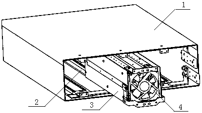
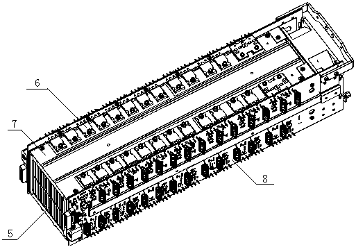
[0015] Example figure 1 with figure 2 As shown, this embodiment provides an electronic load testing device, including a housing 1, a connection board, three electrically insulating guide rails 2, a power module 3 and a main control board, and the main control board controls the power module through the connection board and external testing equipment, a power module 3 is electrically insulated from the housing 1 by means of an electrically insulating guide rail 2 and is installed in the housing 1, and the remaining two electrically insulating guide rails 2 are extended for backup. The power module 3 includes a PCB board 8 , a plurality of power devices 6 and a heat sink 5, the heat dissipation ends of a plurality of power devices 6 are all mounted on the heat sink 5, and the heat dissipation ends on the pins of the power devices 6 are positi...


PUM


Abstract

The invention provides an electronic load testing device. The device includes a housing and one or more power modules, one or more parallelly arranged electric insulation guide rails, the power modules are arranged in the housing through the electric insulation guide rails in electric insulation from the housing in a drawing and inserting mode, each power module includes a PCB, power devices, a graphite flake and a radiator, the radiator arranged to be a positive electrode and a negative electrode on the PCB are connected to a test input end of the electronic load testing device separately, the power devices and the graphite flake are mounted on the radiator in an attached mode, negative ends of the power devices are electrically connected to the PCB, and positive ends of the power devicesare electrically connected to the radiator through the graphite flake. Electrical connection is realized, power density is increased, heat emission is reduced, heat dissipation is enhanced and the volume of the radiator is reduced; and at the same time, relatively good adhesion property is achieved, electrical conductivity is improved, large-area electrical connection between power tubes and theradiator can be realized, the welding of a pin is omitted, and the large-cross section radiator is used as a lead, thereby reducing conventional lead heat emission of whole machine heat emission.

Description

technical field [0001] The invention relates to an electronic load testing device, in particular to an electronic load testing device with high thermal conductivity, high electrical conductivity and easy expansion. Background technique [0002] The electronic load test device is generally used to absorb the power of the power supply during the test of the power supply product. In addition to the DC power supply, the electronic load test device will be used in DC-DC adapters, lithium batteries, fuel cells and solar panels. [0003] At present, with the continuous increase in the power of electronic products to be tested, the volume of the electronic load test device continues to increase, and it is difficult to expand the channel, which occupies limited laboratory space; the main reason is that the power devices of the electronic load test device need high-efficiency heat dissipation. Heat sinks and thermally conductive filling materials affect heat dissipation efficiency, an...

Claims


Application Information

Patent Timeline
Patent Type & Authority Applications(China)
IPC IPC(8): G01R31/00
CPCG01R31/00
Inventor 不公告发明人
Owner ILD ELECTRONICS CO LTD
Learn More