Contactor power saver detecting circuit

A technology for detecting circuits and contactors, applied in circuits, relays, electrical connection tests, etc., can solve problems such as the inconsistency of AC input and DC input operating voltages, and achieve the effect of reducing production and inventory pressure and making circuits simple and easy to use

Pending Publication Date: 2018-08-10
MORNSUN GUANGZHOU SCI & TECH +1
View PDF9 Cites 3 Cited by
  • Summary
  • Abstract
  • Description
  • Claims
  • Application Information

AI Technical Summary

Problems solved by technology

In the case of AC and DC, if simple voltage division sampling and threshold comparison are used, then in the case of AC input, it will be triggered at a lower voltage, resulting in inconsistent operating voltages between AC input and DC input.

Method used


Image

  • Contactor power saver detecting circuit
  • Contactor power saver detecting circuit
  • Contactor power saver detecting circuit

Examples


no. 1 example

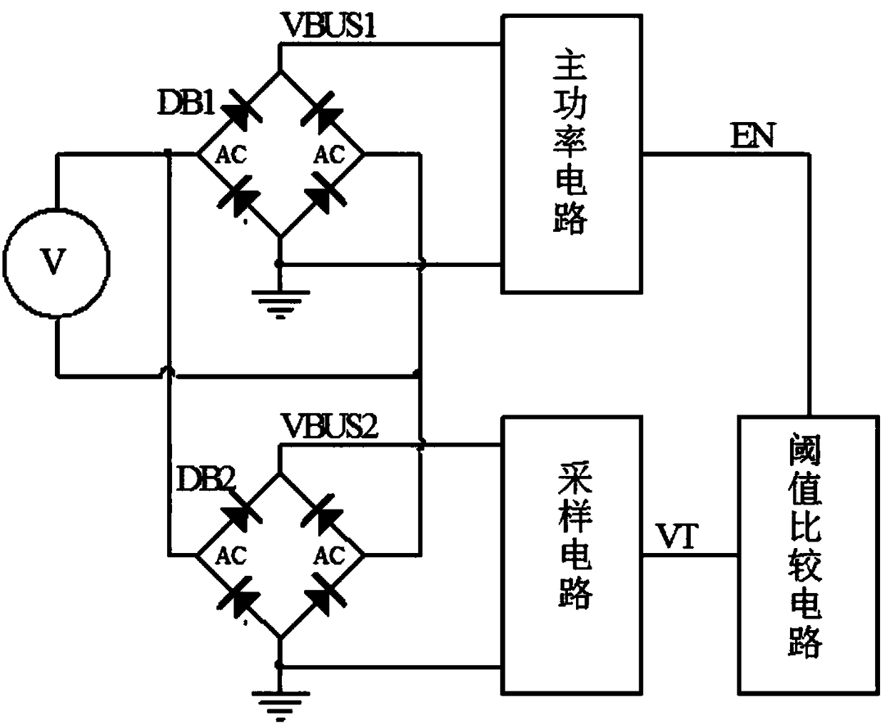
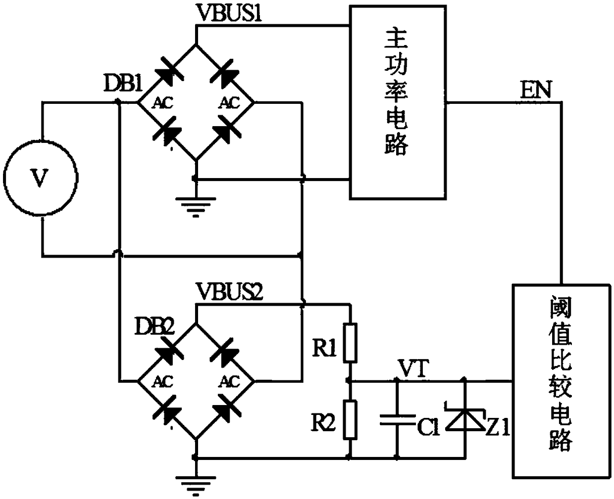
[0051] figure 2 It is a principle diagram of the first embodiment of the present invention, and a general contactor power saver includes a rectifier bridge DB1 and a main power circuit for controlling the current of the contactor coil. This embodiment also includes a rectifier bridge DB2, a resistor R1, a resistor R2, a capacitor C1 and a threshold comparison circuit. The AC input terminals of the rectifier bridge DB1 and the rectifier bridge DB2 are connected in parallel to the input voltage, the positive output terminal VBUS1 of the rectifier bridge DB1 is connected to the main power circuit, and the negative output terminal of the rectifier bridge DB1 is connected to the ground. The positive output terminal VBUS2 of the rectifier bridge DB2 is connected to one end of the resistor R1, the other end of the resistor R1 is connected to one end of the resistor R2, and the connection point of the resistor R1 and the resistor R2 is used as the output terminal to be connected to t...

no. 2 example

[0077] Figure 5 It is the schematic diagram of the second embodiment of the present invention. The difference between the second embodiment and the first embodiment is that the sampling circuit is composed of an inductor L1, a resistor R3 and a resistor R4, and the inductor L1, the resistor R3 and the resistor R4 are connected in series. The terminal forms the input terminal of the sampling circuit, and the connection point of the resistor R3 and the resistor R4 is the output terminal of the sampling circuit. This embodiment also further includes a Zener diode Z1, which is connected in parallel to both ends of the resistor R4, wherein the cathode of the Zener diode Z1 is connected to the connection point of the resistors R3 and R4, and the anode of the Zener diode Z1 is grounded.

[0078] The basic principle of the second embodiment is the same as that of the first embodiment, and the transfer function of the sampling circuit composed of the inductor L1, the resistor R3 and t...

no. 3 example

[0086] Figure 6 It is the schematic diagram of the third embodiment of the present invention. The difference between the third embodiment and the first embodiment is that the rectifier bridge DB2 is replaced by a diode D1 and a diode D2, and the diode D1 and the diode D2 are grounded with the two diodes of the rectifier bridge DB1. form a full wave rectifier circuit. The connection relationship is: the anode of the diode D1 is connected to one end of the AC input AC of the rectifier bridge DB1, and the anode of the diode D2 is connected to the other end of the AC input AC of the rectifier bridge DB1. The cathode of diode D1 and the cathode of diode D2 are connected to one end of resistor R1, and the other end of resistor R1 is connected to one end of resistor R2. It is connected to the negative output terminal of the rectifier bridge DB2 and then grounded, the capacitor C1 is connected in parallel to both ends of the resistor R2, and the threshold comparison circuit is conne...


PUM


Abstract

The invention discloses a contactor power saver detecting circuit. On the basis of the existing contactor power saver circuit composed of a rectifier bridge and a main power circuit, a rectifier circuit, a sampling circuit and a threshold comparison circuit are additionally provided. The threshold comparison circuit is internally provided with a reference 1 and a reference 2. When the peak voltageof an output signal of the sampling circuit is greater than the reference 1, the main power circuit is controlled to work, and a contactor is closed; when the peak voltage of the output signal of thesampling circuit is less than the reference 2, the main power control circuit is switched off, and the contactor is released; it is required that the peak voltage of the output signal of the samplingcircuit when input voltage is AC is equal to the peak voltage of the output signal of the sampling circuit when the input voltage is DC, so that a voltage point that triggers action of the contact isenabled to be the same. Therefore, the object that attracting and releasing voltage points of the wide-input-voltage contactor are consistent under AC / DC input voltages is achieved, and the circuit is simple and easy to use, thereby finally realizing the universality of the AC / DC contactor power saver product, and reducing the production and inventory pressure of the manufacturer.

Description

technical field [0001] The invention relates to the field of AC contactors, and in particular relates to a detection circuit for a power saver of a contactor. Background technique [0002] The traditional contactor operating system consists of a coil, a static iron core, an armature and a reaction spring. When the contactor coil is energized, a suction force is generated between the static iron core and the armature. When the suction force is greater than the spring reaction force, the armature is attracted to the static iron core until it contacts the static iron core. At this time, the main contact is closed. This process is called suction. combined process. The process in which the coil is continuously energized, the armature is in contact with the static iron core, and the main contacts are in a closed state is called the holding process. When the current in the coil is reduced or interrupted, the suction force of the static iron core to the armature decreases. When th...

Claims


Application Information

Patent Timeline
Patent Type & Authority Applications(China)
IPC IPC(8): G01R31/04
CPCG01R31/66H01H47/04H01H47/22
Inventor 苏俊熙
Owner MORNSUN GUANGZHOU SCI & TECH
Why Eureka
Try Eureka