Check patentability & draft patents in minutes with Patsnap Eureka AI!

An optimized mimo radar antenna array design method

A radar antenna and design method technology, applied in the radar field, can solve the problems of difficult MIMO radar antenna advantages, increase the radar volume, waste antenna board area, etc., and achieve the effect of solving layout design difficulties, improving efficiency, and eliminating repeated calculations

Active Publication Date: 2021-07-13
重庆睿行电子科技有限公司
View PDF4 Cites 0 Cited by
  • Summary
  • Abstract
  • Description
  • Claims
  • Application Information

AI Technical Summary

Problems solved by technology

However, since MIMO radar uses multiple transmitting and receiving channels, when the number of transmitting antennas and receiving antennas increases, it is difficult to use the empirical array method to take advantage of the antenna advantages of MIMO radar, which wastes the antenna board area and increases the overall radar volume of

Method used


Image

  • An optimized mimo radar antenna array design method
  • An optimized mimo radar antenna array design method
  • An optimized mimo radar antenna array design method

Examples


Embodiment 1

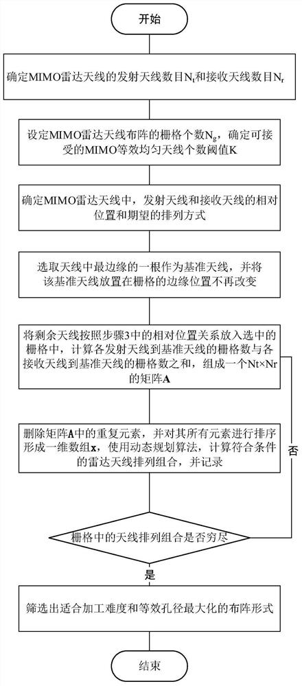
[0036] In this example, an optimized MIMO radar antenna array design method includes the following steps:

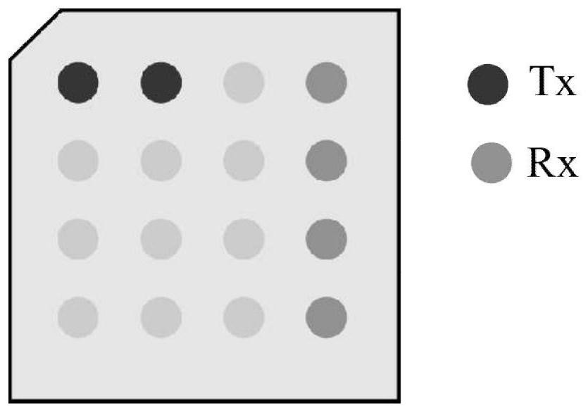
[0037] Set the grid number N of the MIMO radar antenna array g ; Select one of the MIMO radar antennas as the reference antenna and place it in the grid; select N from the remaining grids t +N r -1 grid to place the remaining antennas to form an array, where N t is the number of transmitting antennas, N r is the number of receiving antennas; traverse all array forms, calculate the equivalent antenna structure in all array forms according to the distance between each antenna and the reference antenna, and select the most suitable array form.

[0038] In this example, with the help of computer calculations, a better array layout can be found than the empirical layout, which solves the difficulty of layout design when there are many MIMO antennas.

Embodiment 2

[0040] On the basis of Embodiment 1, in order to avoid repeated calculation of antenna arrays with the same effect, this embodiment selects an antenna at the edge position (i.e., the leftmost or rightmost) of the antennas as the reference antenna, and places the reference antenna in the The edge position in the grid (that is, the leftmost or rightmost in the grid network), and in the subsequent array arrangement process, the grid will not be moved for this antenna.

Embodiment 3

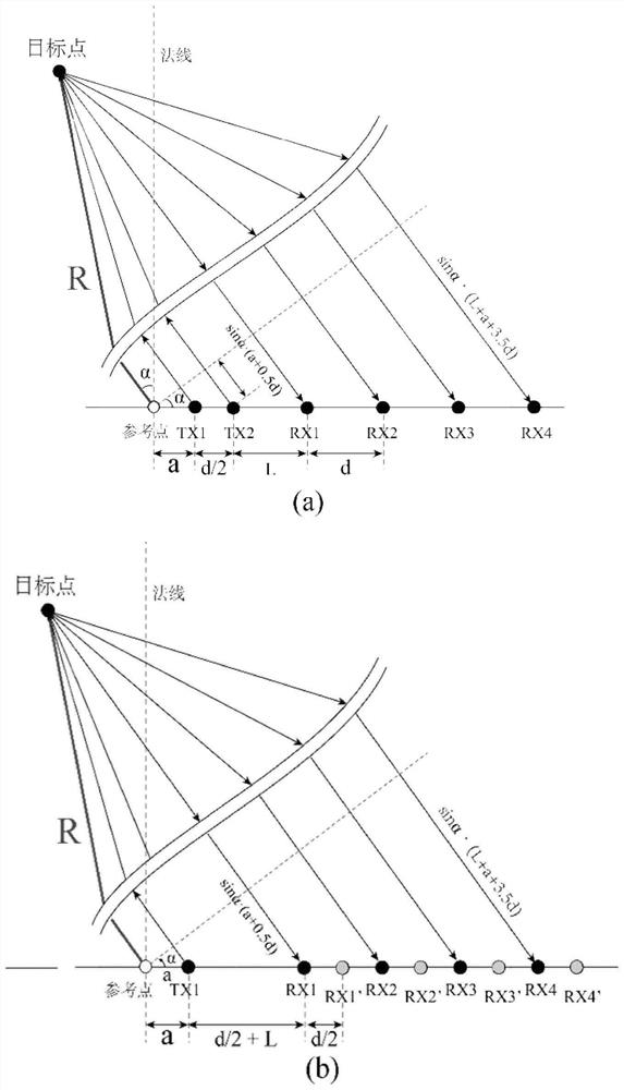
[0042] On the basis of Embodiment 1, the process of calculating the equivalent antenna structure under all array forms is as follows: calculate the grid distance l from each transmitting antenna to the reference antenna i (i=1,2...N t ), calculate the grid distance l from each receiving antenna to the reference antenna j '(j=1,2...N r ), and calculate an N t ×N r matrix Each element of matrix A satisfies Sort the elements in the matrix A, and remove the repeated elements to form a one-dimensional vector x. According to the MIMO calculation rules, use the dynamic programming algorithm to calculate the equivalent antenna structure in this array form.


PUM


Abstract

The present invention provides an optimized MIMO radar antenna array design method, comprising the following steps: setting the grid number N of the MIMO radar antenna array g ; Select one of the MIMO radar antennas as the reference antenna and place it in the grid; select N from the remaining grids t +N r ‑1 grid to place the remaining antennas to form an array, where N t is the number of transmitting antennas, N r is the number of receiving antennas; traverse all array forms, calculate the equivalent antenna structure in all array forms according to the distance between each antenna and the reference antenna, and select the most suitable array form. The present invention is aimed at all the layout forms, with the help of computer calculations, it can find a better layout effect than the empirical layout, solves the difficulty of layout design when there are many MIMO antennas, and can give full play to the performance of the radio frequency chip and make full use of the radio frequency board area.

Description

technical field [0001] The invention belongs to the technical field of radar, and in particular relates to an optimized MIMO radar antenna array design method. Background technique [0002] Multiple-input multiple-output (MIMO) radar is an emerging radar technology. Compared with traditional real-aperture radars, MIMO radars use multiple transmit channels and multiple receive channels to form a larger antenna aperture, thereby improving the spatial resolution capability. By using digital beamforming technology, multiple targets in the scene can be detected. Simultaneous detection. However, since MIMO radar uses multiple transmitting and receiving channels, when the number of transmitting antennas and receiving antennas increases, it is difficult to use the empirical array method to take advantage of the antenna advantages of MIMO radar, which wastes the antenna board area and increases the overall radar volume of. Contents of the invention [0003] In view of this, the ...

Claims


Application Information

Patent Timeline
Patent Type & Authority Patents(China)
IPC IPC(8): G06F30/20
CPCG06F30/00
Inventor 姜海涛刘建虎赵通刘峰
Owner 重庆睿行电子科技有限公司
Features
  • R&D
  • Intellectual Property
  • Life Sciences
  • Materials
  • Tech Scout
  • Unparalleled Data Quality
  • Higher Quality Content
  • 60% Fewer Hallucinations
Learn More