Rapid sewage discharge and precipitation device and method for rapid settlement and recovery

A rapid sewage discharge and rapid technology, applied in separation methods, chemical instruments and methods, settling tanks, etc., can solve the problems of long installation time, no need to have water first, or unable to build masonry, and many installation procedures, etc., to speed up The effect of cleaning time, speeding up the investment of pumping time, and reducing the labor intensity of workers

Active Publication Date: 2018-08-14
CHINA FIRST METALLURGICAL GROUP
View PDF6 Cites 2 Cited by
  • Summary
  • Abstract
  • Description
  • Claims
  • Application Information

AI Technical Summary

Problems solved by technology

The old method in drainage construction requires masonry to build a sedimentation tank, install a submersible pump, a power control box and a float switch, connect cables, cover the drain pipe with a grid plate, and then divert water to the sedimentation tank. (The sedimentation tank cannot have water first. , or it cannot be masonry) Finally, the drainage work can be carried out. During the drainage period, the 1-2 level sedimentation tank needs to be manually dredged regularly. This drainage method has many installation procedures and takes a long time
The construction of the section still needs to be completed, and the temporary drainage facilities, grilles, drainage pipes, and electric control boxes need to be removed. The blocks of the sedimentation tank will become garbage and must be cleaned out of the site, which is not environmentally friendly.

Method used


Image

  • Rapid sewage discharge and precipitation device and method for rapid settlement and recovery
  • Rapid sewage discharge and precipitation device and method for rapid settlement and recovery
  • Rapid sewage discharge and precipitation device and method for rapid settlement and recovery

Examples


Embodiment Construction

[0026] In order to better understand the present invention, below in conjunction with embodiment and accompanying drawing, technical scheme of the present invention is described further (as Figure 1-3 shown).

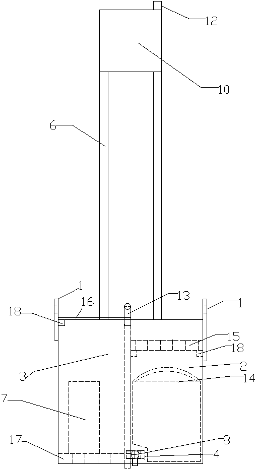
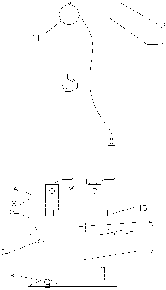
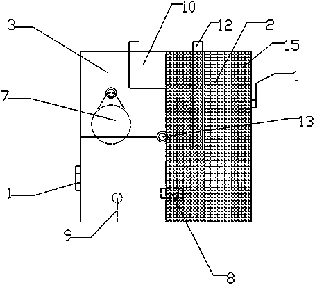
[0027] A rapid sewage discharge and precipitation device for rapid installation and recovery, which includes a 2-3 stage sedimentation tank box and a boom part;

[0028] The inside of the 2-3 level sedimentation tank box (the 2-3 level sedimentation tank box is a cuboid steel box structure) is divided into the third-level sedimentation tank 3 and the second-level sedimentation tank 2, and the third-level sedimentation tank The upper part (steel plate) between 3 and the secondary sedimentation tank 2 is connected through an overflow port 5; the bottom of the 2-3 sedimentation tank box is provided with a three-way valve 8, and the three ports of the three-way valve 8 are respectively connected to three Three-way valve 8 is provided with a three-way valve plug 4 on the o...


PUM


Abstract

The invention relates to a rapid sewage discharge and precipitation device for rapid settlement and recovery. The rapid sewage discharge and precipitation device comprises a 2-3-stage sedimentation pond tank and a suspender part. The 2-3-stage sedimentation pond tank is divided into a left third-stage sedimentation pond and a right second-stage sedimentation pond, and the third-stage sedimentationpond and the second-stage sedimentation pond are communicated through an overflow port. A three-way valve is arranged at the bottom of the 2-3-stage sedimentation pond, and a three-way valve pipe plug is arranged on the three-way valve. A hoisting lug is arranged on the 2-3-stage sedimentation pond tank. A submersible pump is arranged inside the third-stage sedimentation pond. The upper part of the second-stage sedimentation pond is provided with an opening, the opening is provided with a first glass fiber reinforced plastic grating plate, and a hoisting woven bag is sleeved with the second-stage sedimentation pond. The suspender part comprises a vertical rod, a transverse rod and a power control box. The vertical rod is vertically fixed on the 2-3-stage sedimentation pond tank, and the upper end of the vertical rod is fixedly connected with the transverse rod. A suspension type electric hoist is installed on the transverse rod. The power control box is installed at the upper end of the vertical rod. According to the rapid sewage discharge and precipitation device, a crane is used for installation, so that the labor intensity of workers is reduced, and the cleaning time is shortened.

Description

technical field [0001] The invention relates to the field of municipal engineering construction, in particular to a rapid sewage discharge and dewatering device and method for rapid installation and recovery. Background technique [0002] In the field of municipal engineering construction, due to underground water seepage, cement maintenance, rain and other conditions that cause water accumulation in foundation pits, drainage is required in many places, and the water discharged into urban sewage wells is not allowed to have sediment and floating objects, and it needs to settle before it can be drained. Remove standing water. The old method in drainage construction requires masonry to build a sedimentation tank, install a submersible pump, a power control box and a float switch, connect cables, cover the drain pipe with a grid plate, and then divert water to the sedimentation tank. (The sedimentation tank cannot have water first. , or it cannot be masonry) Finally, the drain...

Claims


Application Information

Patent Timeline
Patent Type & Authority Applications(China)
IPC IPC(8): E02D19/06E02D19/10B01D21/00B01D21/02
CPCB01D21/0012B01D21/003B01D21/02E02D19/06E02D19/10
Inventor 陈俊夏明胡燕立季华锋李潇葆吴云飞张俊
Owner CHINA FIRST METALLURGICAL GROUP
Why Eureka
Try Eureka