Multilayer linkage type side sealing device for fuel gas blowing and sintering, and control method thereof

A technology of a sealing device and a blowing device, which is applied in the field of sintering, can solve the problems of tearing and tearing of gas pipelines, easy accumulation of dust, negative effect of gas injection auxiliary sintering, etc.

Pending Publication Date: 2018-08-14
ZHONGYE-CHANGTIAN INT ENG CO LTD
View PDF18 Cites 3 Cited by
  • Summary
  • Abstract
  • Description
  • Claims
  • Application Information

AI Technical Summary

Problems solved by technology

[0006] 1. The sealing effect is not good: because the side sealing device of the blowing hood in the prior art is a single-layer side seal, that is, there is only one layer of side sealing plate, so when the negative pressure inside the hood is large or the ambient wind speed near the blowing hood is high At this time, the side seal cannot play a good sealing role, so that the cold air leaks in from the side of the blowing hood, which has a negative effect on the auxiliary sintering effect of gas injection;
[0007] 2. Easy to accumulate dust: Since the sintering workshop is a dusty and powdery environment, during long-term production, dust is easy to accumulate between the sealing plate of the side seal device and the fence of the sintering machine trolley. If it cannot be found in time and effectively After a long time, it will form a large piece of dirt, which will be sandwiched between the trolley fence and the sealing plate. Once the trolley fence is tilted out due to various reasons, the dirt will make the side sealing plate Driven by the trolley to run forward, the whole set of injection device is driven forward with the trolley, which in turn causes the gas pipeline connected to the injection device to be torn apart, causing serious production safety accidents

Method used


Image

  • Multilayer linkage type side sealing device for fuel gas blowing and sintering, and control method thereof
  • Multilayer linkage type side sealing device for fuel gas blowing and sintering, and control method thereof
  • Multilayer linkage type side sealing device for fuel gas blowing and sintering, and control method thereof

Examples


Embodiment approach

[0092] According to the first embodiment provided by the present invention, a multi-layer interlocking side sealing device for gas injection sintering is provided.

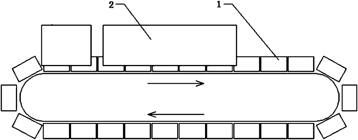
[0093] A multi-layer linkage side sealing device for gas injection sintering, the device includes a sintering machine trolley 1, a sealing cover 2, a gas injection device 3, and a side sealing device 4. The sintering machine trolley 1 is located in the sealed cover 2 . The gas injection device 3 is located above the sintering machine trolley 1 . The device is provided with a multilayer side seal 4 . The multi-layer side sealing device 4 is arranged between the two sides of the sintering machine trolley 1 and the inner surface of the sealing cover 2 . The side sealing device 4 includes a connecting rod 401 , a rotating shaft 402 , a bearing plate 403 and a sealing plate 404 . One end of the connecting rod 401 is connected to the inner side of the sealing cover 2 . The other end of the connecting rod 401 is prov...

Embodiment 1

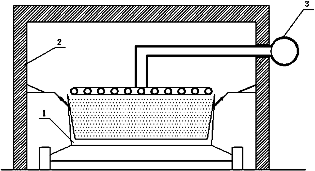
[0110] Such as Figure 3-4 As shown, a multi-layer linkage side sealing device for gas injection sintering, the device includes a sintering machine trolley 1, a sealing cover 2, a gas injection device 3, and a side sealing device 4. The sintering machine trolley 1 is located in the sealed cover 2 . The gas injection device 3 is located above the sintering machine trolley 1 . The device is provided with a multilayer side seal 4 . The multi-layer side sealing device 4 is arranged between the two sides of the sintering machine trolley 1 and the inner surface of the sealing cover 2 . The side sealing device 4 includes a connecting rod 401 , a rotating shaft 402 , a bearing plate 403 and a sealing plate 404 . One end of the connecting rod 401 is connected to the inner side of the sealing cover 2 . The other end of the connecting rod 401 is provided with a rotating shaft 402 . The bearing plate 403 is connected with the rotating shaft 402 . The sealing plate 404 is connected w...

Embodiment 2

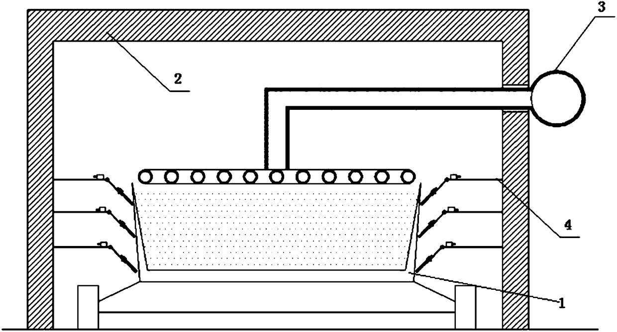
[0112] Such as Figure 5-6As shown, a multi-layer linkage side sealing device for gas injection sintering, the device includes a sintering machine trolley 1, a sealing cover 2, a gas injection device 3, and a side sealing device 4. The sintering machine trolley 1 is located in the sealed cover 2 . The gas injection device 3 is located above the sintering machine trolley 1 . The device is provided with three layers of side sealing devices 4 . The three layers of side sealing devices 4 are arranged between the two sides of the sintering machine trolley 1 and the inner surface of the sealing cover 2 . The side sealing device 4 includes a connecting rod 401 , a rotating shaft 402 , a bearing plate 403 and a sealing plate 404 . One end of the connecting rod 401 is connected to the inner side of the sealing cover 2 . The other end of the connecting rod 401 is provided with a rotating shaft 402 . The bearing plate 403 is connected with the rotating shaft 402 . The sealing plate ...


PUM


Abstract

The invention relates to a multilayer linkage type side sealing device for fuel gas blowing and sintering. The device comprises a sintering pallet, a sealing cover, a fuel gas blowing device and sidesealing devices. The sintering pallet is located in the sealing cover. The fuel gas blowing device is located above the sintering pallet. The device is provided with multiple layers of side sealing devices. The multiple layers of side sealing devices are arranged between two sides of the sintering pallet and the inner side surface of the sealing cover. Each side sealing device comprises a connecting rod, a rotary shaft, a loading plate and a sealing plate. One end of each connecting rod is connected with the inner side of the sealing cover. Each rotary shaft is arranged at the other end of thecorresponding connecting rod. Each loading plate is connected with the corresponding rotary shaft. Each sealing plate is connected with the corresponding loading plate. The tail end of each sealing plate is close to the outer side surface of the sintering pallet. According to the multilayer linkage type side sealing device for fuel gas blowing and sintering provided by the invention, a sealing effect can be effectively ensured, deposited ash can be effectively cleaned, and the aims of stable yield and smooth production of a whole coal gas blowing auxiliary sintering production line are achieved.

Description

technical field [0001] The invention relates to a side sealing device and a control method thereof, in particular to a multilayer linkage type side sealing device for gas injection and a control method thereof, belonging to the technical field of sintering. Background technique [0002] The sintering process is a key link in the ironmaking process. Its principle is to mix various powdery iron-containing raw materials with an appropriate amount of fuel and flux, add an appropriate amount of water, mix and pelletize the material on the sintering equipment to make the material A series of physical and chemical changes, sintered into blocks, which are sent to the blast furnace for the next step. [0003] In order to reduce the coke ratio and smelting cost of blast furnace ironmaking, blast furnaces often require high strength and high reducibility for sinter. In the sintering process, the sintered ore is generally required to have high strength, high yield, low return rate, and...

Claims


Application Information

Patent Timeline
Patent Type & Authority Applications(China)
IPC IPC(8): F27B21/08F27B21/14F27D99/00
CPCF27B21/00F27D99/0073F27M2003/04
Inventor 周浩宇刘前
Owner ZHONGYE-CHANGTIAN INT ENG CO LTD
Why Eureka
Try Eureka