Substrate processing apparatus, control method therefor, and computer readable storage medium

A substrate processing device and processing liquid technology, which is applied in semiconductor/solid-state device manufacturing, electrical components, circuits, etc., and can solve the problems of substrate processing device complexity and size

Active Publication Date: 2018-08-14
DAINIPPON SCREEN MTG CO LTD
View PDF10 Cites 2 Cited by
  • Summary
  • Abstract
  • Description
  • Claims
  • Application Information

AI Technical Summary

Problems solved by technology

[0009] However, for example, with the installation of a camera system for monitoring, there is a possibility of complicating and increasing the size of the substrate processing equipment.

Method used


Image

  • Substrate processing apparatus, control method therefor, and computer readable storage medium
  • Substrate processing apparatus, control method therefor, and computer readable storage medium
  • Substrate processing apparatus, control method therefor, and computer readable storage medium

Examples


no. 1 approach

[0160]

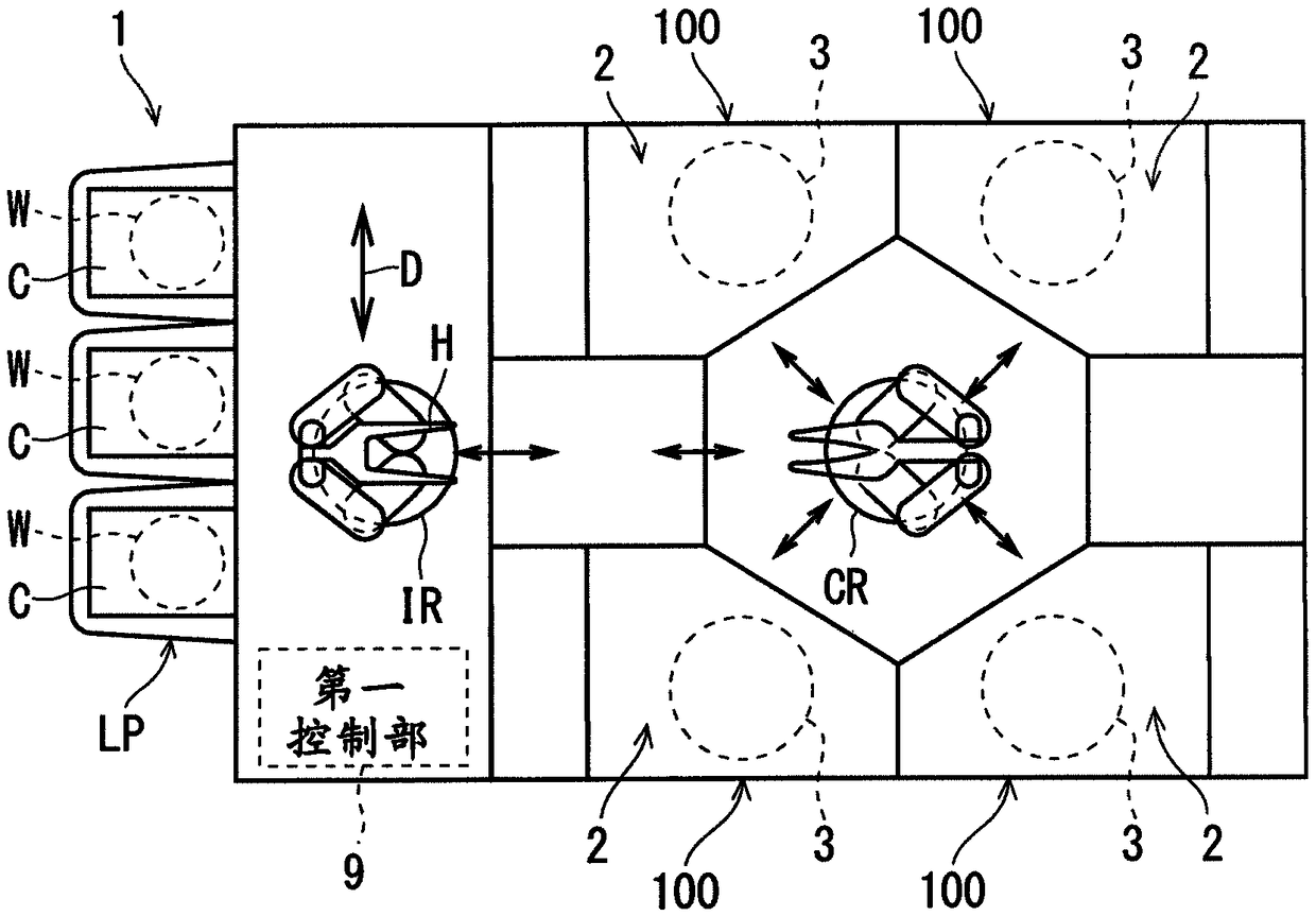
[0161] figure 1 It is a schematic plan view showing an example of a schematic configuration of the substrate processing apparatus 1 of the first embodiment. The substrate processing apparatus 1 is, for example, a single-wafer type apparatus capable of performing various processes by supplying a processing liquid to the surface of a semiconductor substrate (wafer) as an example of a substrate W. Various treatments include, for example, chemical solution treatment for etching with a chemical solution, cleaning treatment for removing contaminants with a liquid, rinsing treatment for rinsing with water, and coating treatment for applying a resist or the like.

[0162] The substrate processing apparatus 1 includes a load port LP as a container holding mechanism that holds a plurality of carriers C as containers, and a plurality (twelve in this embodiment) of processing units 100 that process a substrate W. Specifically, for example, three sets of processing units 100 e...

no. 3 approach

[0281] In each of the above-described embodiments, for example, as the liquid suction operation, suction by a siphon system or suction by a vacuum generator may be used instead of suction by a diaphragm system. The suction of the siphon method and the suction of the vacuum generator method are to suck back and discharge the processing liquid Lq1 present in the part from the discharge valve 51 to the nozzle Nz1 in the piping part P1 when the processing liquid Lq1 discharged from the nozzle Nz1 is replaced. Liquid suction action.

[0282] Figure 12 It is a diagram schematically showing a configuration example of the processing unit 100 of the third embodiment. Such as Figure 12 As shown, as the processing unit 100 of the third embodiment, for example, based on the processing unit 100 of the first embodiment, the processing liquid supply system 5 is replaced with the processing liquid supply system 5B.

[0283] As the processing liquid supply system 5B, for example, based on...

no. 4 approach

[0307] In the third embodiment described above, for example, as Figure 13 As shown, the detection unit 55B may be changed to a detection unit 55C that detects the presence of the processing liquid Lq1 in the piping portion P1B or a specific state related to the flow rate. With this change, the processing liquid supply system 5B is set to the processing liquid supply system 5C. Figure 13 It is a diagram schematically showing a configuration example of the processing unit 100 of the fourth embodiment.

[0308] Here, as the specific state related to the presence of the processing liquid Lq1 in the piping portion P1B, for example, a state in which the liquid level of the processing liquid Lq1 reaches a specific position of the branch pipe portion P1d (also referred to as a specific suck-back state) is used. In this case, for example, if the first branched pipe portion P1d1 is formed of a transparent or semi-transparent pipe, the detecting portion 55C may be arranged to face a s...


PUM


Abstract

The invention provides a substrate processing apparatus, a control method therefor, and a computer readable storage medium, which suppress occurrence of defects when discharging a treatment liquid from a nozzle to a substrate via a relatively simple structure. The substrate processing apparatus includes a nozzle, a piping portion, a valve, an activating portion, a control portion, and a detectingportion. The nozzle discharges the treatment liquid to the substrate. The piping portion forms a flow path of the treatment liquid connected to the nozzle. The valve is provided at a midway portion ofthe piping portion, and changes the existence state of the treatment liquid in the piping portion and the nozzle. The activating portion imparts a driving force to the valve to operate the valve. Thecontrol portion operates the valve through the activating portion by outputting a trigger signal. The detecting portion detects a specific state. The control portion calculates the amount of change in the setting relating to the operating speed of the valve operation caused by the activating portion based on the relationship between the actual operating time from the first timing when the triggersignal is output to the second timing when detecting portion detects the specific state and the reference operating time.

Description

technical field [0001] The invention relates to a substrate processing device, a control method of the substrate processing device and a computer-readable storage medium. The substrates to be processed include, for example, semiconductor substrates, substrates for liquid crystal display devices, substrates for plasma displays, substrates for FED (Field Emission Display, field emission displays), substrates for optical discs, Substrates for magnetic disks, substrates for magneto-optical disks, substrates for photomasks, ceramic substrates, substrates for solar cells, etc. Background technique [0002] In the substrate processing apparatus, the supply path of the processing liquid to the nozzle is opened and closed by a discharge valve provided in the middle of a pipe connected to the nozzle. Thereby, discharge of the processing liquid from the nozzle to the substrate is started and stopped. [0003] In such a substrate processing apparatus, a phenomenon in which the process...

Claims


Application Information

Patent Timeline
Patent Type & Authority Applications(China)
IPC IPC(8): H01L21/67
CPCH01L21/67023H01L21/67051H01L21/6708H01L21/6715H01L21/67253H01L21/67242H01L21/02052
Inventor 中井仁司
Owner DAINIPPON SCREEN MTG CO LTD
Why Eureka
Try Eureka