
Hydraulic winching

A winching and hydraulic technology, applied in fluid pressure actuation devices, fluid pressure actuation system components, servo motors, etc., can solve the problems of hidden safety hazards in line construction, few speed gears, large volume, etc., and achieve traction speed and Wide traction range, avoid equipment damage, high transmission efficiency

Pending Publication Date: 2018-08-17
YANGZHOU GUODIAN TONGYONG MFG
View PDF0 Cites 5 Cited by
  • Summary
  • Abstract
  • Description
  • Claims
  • Application Information

AI Technical Summary

Problems solved by technology

Large and medium-sized hydraulic tractors are bulky and heavy, and working for a long time will cause the oil temperature to rise, which will affect the normal use of the equipment. Construction in mountainous areas requires special mountain roads and special traction yards. Field work is very inconvenient
Although the construction cost of large and medium-sized hydraulic tractors is high, hydraulic tractors are safe, reliable and efficient when used, and they are indispensable construction equipment in wire-stretching construction.
Although the ordinary mechanical single-drum motorized winch mill is small in size and light in weight, it has slow traction speed, few speed gears, and low construction efficiency.
And during the construction, the steel wire ropes will squeeze and wear each other on the single drum, the braking lag (running) and the machine will be damaged due to no protective device during overload, which will bring great safety hazards to the line construction.

Method used


Image

  • Hydraulic winching
  • Hydraulic winching
  • Hydraulic winching

Examples


Embodiment Construction

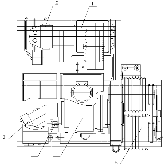
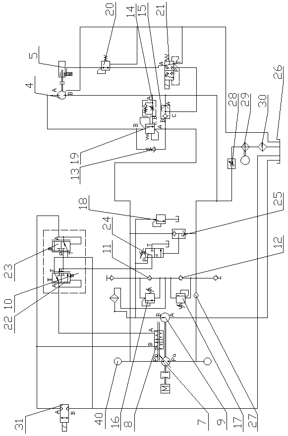
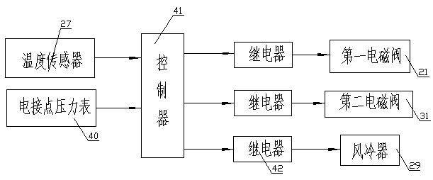
[0023] Such as figure 1 , 2 As shown, the present invention includes a gasoline engine 1, a hydraulic pump 2, a hydraulic motor 3, a speed reducer 4, a hydraulic brake 5, a winch mill cylinder 6 and a hydraulic system for controlling the hydraulic pump 2, the hydraulic motor 3, and the hydraulic brake 5. The gasoline engine 1 The power transmission end of the hydraulic pump 2 is connected, the output end of the hydraulic motor 3 is connected to the grinding cylinder 6 through the reducer 4, the hydraulic brake 5 is connected to the output end of the hydraulic motor 3, and the grinding cylinder 6 belongs to the prior art, which is divided into single twisting The specific structure of the grinding cylinder and the twisted grinding cylinder will not be repeated here.

[0024] The hydraulic pump 2 is a closed variable displacement plunger pump, including a main pump 7, a variable control cylinder 8 and an auxiliary pump 9, and the hydraulic brake 5 is a normally closed hydraulic...


PUM


Abstract

The invention discloses a hydraulic winching and relates to the field of transmission line construction equipment. The hydraulic winching comprises a gasoline engine, a hydraulic pump, a hydraulic motor, a reducer, a hydraulic brake, a winching barrel and a hydraulic system for controlling the hydraulic pump, the hydraulic motor and the hydraulic brake; the hydraulic system comprises a pilot-controlled handle, a hydraulic pump, a hydraulic motor, a hydraulic brake, a first one-way valve, a second one-way valve, a third one-way valve, a one-way throttle valve, a first shuttle valve, a first overflow valve, a second overflow valve, a third overflow valve, a balancing valve, a reducing valve and a first electromagnetic reversing valve. The hydraulic pump is a closed variable plunger pump which comprises a main pump, a variable control oil cylinder and an auxiliary pump; the hydraulic brake is a normally closed pilot-controlled brake; a pressure-controlled handle comprises a first controlvalve and a second control valve. The hydraulic winching disclosed by the invention is high in transmission efficiency, small in size, light in weight and high in traction speed and wide in traction range, can fit various complicated construction conditions, and has an intelligent heat-dissipating system, an overload protecting function and an over-pressure protection function.

Description

technical field [0001] The invention relates to the field of power transmission line construction equipment, in particular to a hydraulic winch mill. Background technique [0002] Tractor equipment is very important construction equipment in the construction of transmission line towers, wire erection and cableway transportation. The tractors used at this stage mainly include large and medium-sized hydraulic tractors and ordinary single-drum motorized winches. Large and medium-sized hydraulic tractors are bulky and heavy, and working for a long time will cause the oil temperature to rise, which will affect the normal use of the equipment. Construction in mountainous areas requires special mountain roads and special traction yards. Field work is very inconvenient. Although the construction cost of large and medium-sized hydraulic tractors is high, hydraulic tractors are safe, reliable and efficient when used, and they are indispensable construction equipment in wire-stretchi...

Claims


Application Information

Patent Timeline
Patent Type & Authority Applications(China)
IPC IPC(8): B66D1/08F15B11/08F15B13/02F15B21/04
CPCF15B11/08F15B13/021F15B21/041F15B21/042B66D1/08
Inventor 姚斌
Owner YANGZHOU GUODIAN TONGYONG MFG
Learn More