Rotary drilling tooth of rotary drilling machine

A rotary digging machine and root technology, applied in the field of rotary digging teeth, can solve problems such as shortened service life of rotary digging teeth, stuck rotary digging teeth, failure to form spin, etc., and achieve the effect of improving the holding force

Inactive Publication Date: 2018-08-17
浏阳湘德机械制造厂
View PDF7 Cites 1 Cited by
  • Summary
  • Abstract
  • Description
  • Claims
  • Application Information

AI Technical Summary

Problems solved by technology

However, in the prior art, due to the extremely harsh working environment, debris and mortar easily enter the tooling gap between the rotary digging tooth and the rotary digging tooth seat, resulting in the rotary digging tooth being stuck in the rotary digging tooth seat and unable to form spin, resulting in eccentric wear
[0005] Therefore, the above-mentioned factors have led to a greatly shortened service life of the rotary digging teeth

Method used


Image

  • Rotary drilling tooth of rotary drilling machine
  • Rotary drilling tooth of rotary drilling machine
  • Rotary drilling tooth of rotary drilling machine

Examples


Embodiment 1

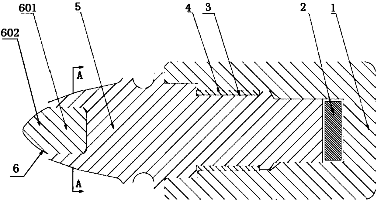
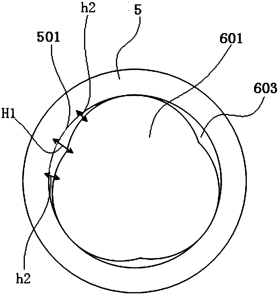
[0017] Embodiment 1: referring to accompanying drawing, reflect a kind of concrete structure of the present invention, the head device cemented carbide rod 6 of the rotary digging tooth 5 of described rotary digging machine, the cylindrical root of rotary digging tooth 5 is equipped with sleeve card The spring 4 and the sleeve spring 4 are pressed into the slot 3 of the inner cavity of the rotary digging tooth holder 1, thereby restricting the axial relative movement of the rotary digging tooth 5 and the rotary digging tooth holder 1, and realizing the rotation of the rotary digging tooth 5 and the rotary digging tooth holder 1. The rotatable sleeve connection between the tooth holders 1 . A gasket 2 is installed between the end face of the cylindrical root of the rotary digging tooth 5 and the end face of the rotary digging tooth seat 1 inner cavity. During the work of the rotary digging gear, as the bucket drill bit goes deeper into the excavation surface, the mud and rock m...

Embodiment 2

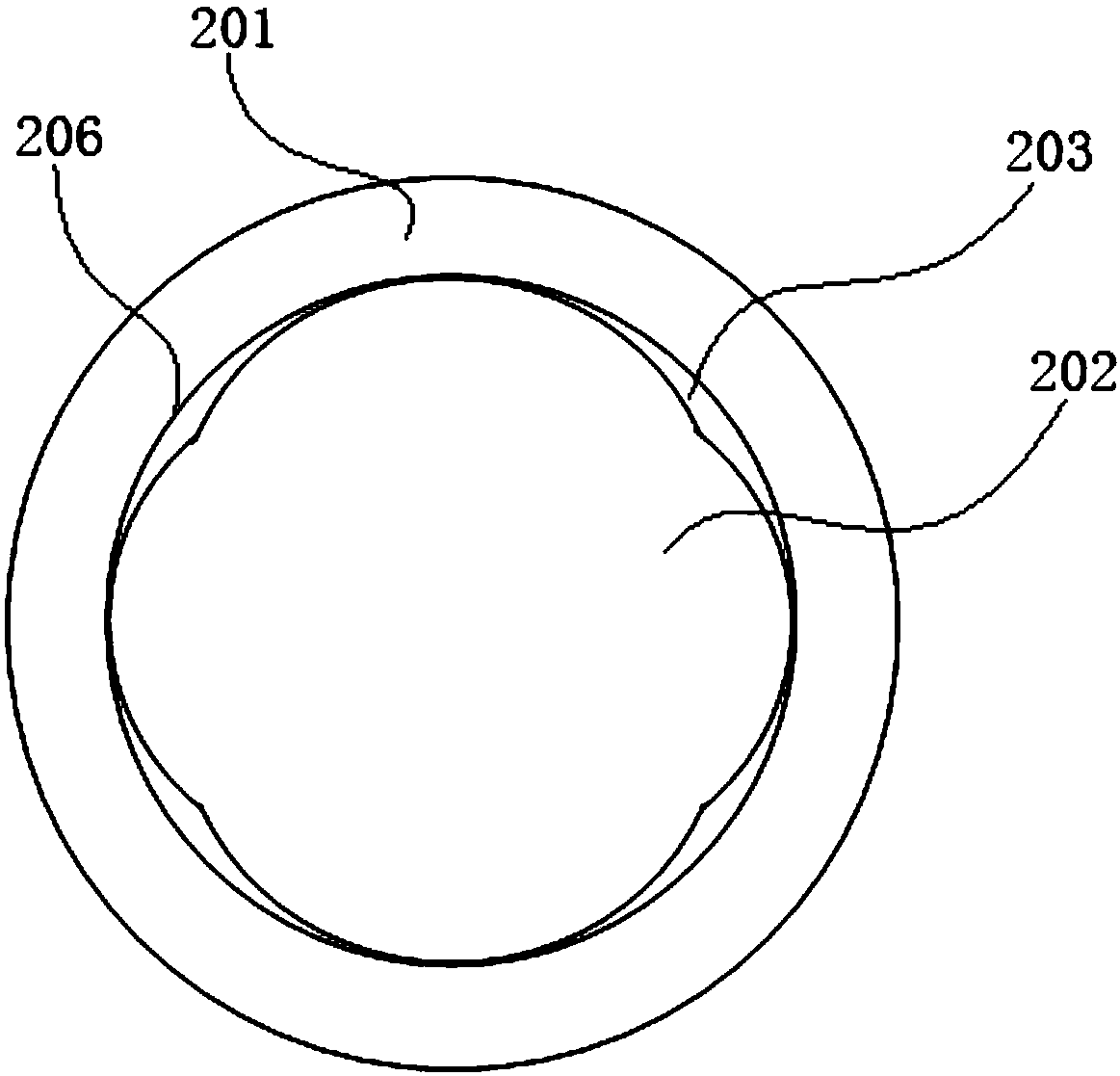
[0020] Example 2: see image 3 The root 202 of the cemented carbide rod is inserted into the mounting hole 206 of the rotary digging tooth 201. The difference from Embodiment 1 is that the number of grooves 203 evenly distributed in the circumferential direction on the side of the root 202 is four.

Embodiment 3

[0021] Embodiment 3: see Figure 4 The root 302 of the cemented carbide rod is inserted into the mounting hole 306 of the rotary digging tooth 301. The difference from Embodiment 1 is that the number of grooves 303 evenly distributed in the circumferential direction of the root 302 is four. The groove 303 is an arc groove, and the cross section of the root 302 constitutes as Figure 4 The arc notch shown is circular, not quincunx.


PUM


Abstract

The invention discloses a rotary drilling tooth of a rotary drilling machine. The rotary drilling tooth is provided with a mounting hole, a cemented carbide rod is composed of a root part and a working part, the root part of the cemented carbide rod is inserted into the mounting hole, and the mounting hole and the root part of the cemented carbide rod are assembled through thermal interference fit. Assembly connection can be completed without brazing, the rotary drilling tooth does not need to be subjected to high-temperature annealing at a copper melting point, and the hardness and wear resistance are not damaged by assembly; in cooperation with tight and non-weak areas, the increase of the holding force of the inner wall of the mounting hole to the outer wall of the root part of a rod body is facilitated, and the cemented carbide rod cannot fall off in a harsh working environment.

Description

technical field [0001] The invention relates to a rotary digging tooth on a rotary excavator. Background technique [0002] Rotary excavator is also called rotary drilling rig and pile driver. Rotary drilling to form a hole is first of all through the drilling rig's own walking function and the mast luffing mechanism to make the drilling tool correctly positioned to the pile position, and use the mast to lower the drill pipe to place the bucket (barrel) drill bit with a valve at the bottom. Put it in the hole position, the power head device of the drilling rig provides torque for the drill pipe, and the pressure device transmits the pressure to the drill pipe bit through the pressurization power head, and the drill bit rotates to break the rock and soil, and directly loads it into the drill bit, and then Then the drill bit is lifted out of the hole by the lifting device of the drilling rig and the telescopic drill pipe to unload the soil. This cycle is repeated, and the soi...

Claims


Application Information

Patent Timeline
Patent Type & Authority Applications(China)
IPC IPC(8): E21B10/43
CPCE21B10/43
Inventor 蒋德定
Owner 浏阳湘德机械制造厂
Why Eureka
Try Eureka