Reading circuit of non-refrigeration infrared focal plane detector and method for improving yield

A focal plane detector, uncooled infrared technology, applied in electrical radiation detectors, radiation pyrometry, instruments, etc., can solve the problem of inability to repair blind elements or reference elements, poor real-time performance, and increased image processing calculations. and other problems, to achieve real-time correction of non-uniformity, avoid column bad line phenomenon, and improve device yield.

Active Publication Date: 2018-08-17
WUHAN GUIDE INFRARED CO LTD
View PDF8 Cites 8 Cited by
  • Summary
  • Abstract
  • Description
  • Claims
  • Application Information

AI Technical Summary

Problems solved by technology

However, since the existing infrared focal plane array devices generally adopt the method of row gating and column output to design the readout circuit, this method can only obtain the arithmetic mean according to the surrounding signal values ​​after the signal values ​​of all effective elements are uploaded. value, the real-time performance is not strong, and the calculation of this method is complicated through multi-point calibration. Once the effective elements around the fault effective element cannot work normally, the calculation amount of image processing will further increase, the efficiency will be lower, the speed will be slower, and the processing result will also be poor. Unreliable
[0012] Since the image processing algorithm can only process the final incident infrared radiation response value, but the blind element or reference element has no response to the incident infrared radiation, so when the blind element resistance or the reference element resistance of the readout circuit fails, the image processing technology is difficult. Correct or assign values ​​to the faulty blind or reference elements, and the blind or reference elements cannot be repaired according to the image processing algorithm, thereby improving the device yield

Method used


Image

  • Reading circuit of non-refrigeration infrared focal plane detector and method for improving yield
  • Reading circuit of non-refrigeration infrared focal plane detector and method for improving yield

Examples


Embodiment Construction

[0049] In order to make the object, technical solution and advantages of the present invention clearer, the present invention will be further described in detail below in conjunction with the accompanying drawings and embodiments. It should be understood that the specific embodiments described here are only used to explain the present invention, not to limit the present invention. In addition, the technical features involved in the various embodiments of the present invention described below can be combined with each other as long as they do not constitute a conflict with each other.

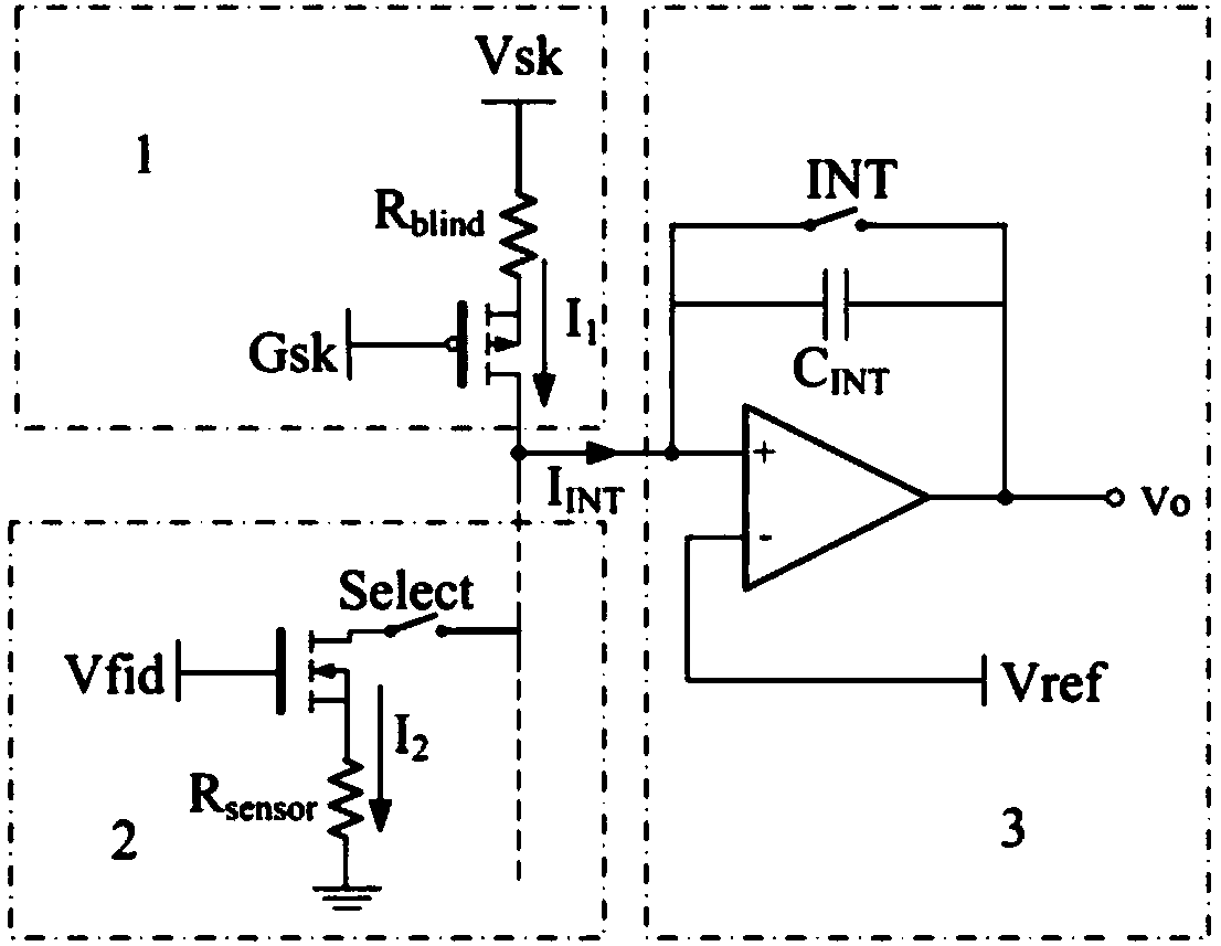
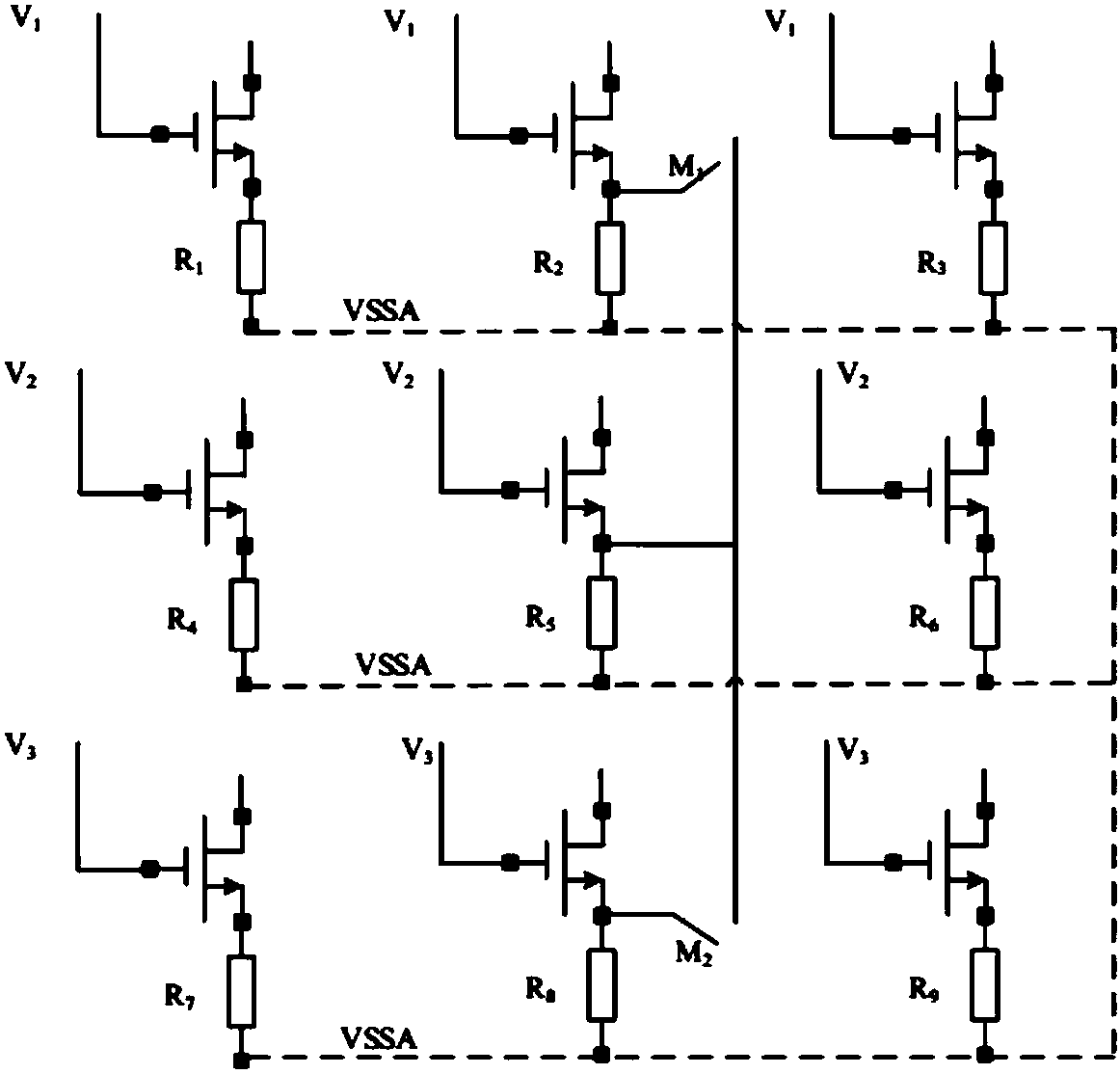
[0050] According to one embodiment of the present invention, a readout circuit of an uncooled infrared focal plane detector is provided, which includes a pixel array, and the pixel array includes M rows×N columns of effective element circuits, and each column also includes a blind Each row also includes a reference element circuit, the current of each effective element circuit is mirrored by the...


PUM


Abstract

The invention discloses a reading circuit of a non-refrigeration infrared focal plane detector and a method for improving the yield. An effective element circuit array is subjected to row gating and column integration through a control module, and a substitute signal is obtained according to the fault signal of the effective element circuit. Effective element resistors and fault effective elementresistors of adjacent rows are connected in parallel, so that the fault effective element circuit works normally, and the image elements of infrared images can be restored in real time. Further, a substitute signal is obtained according to the fault signal of a blind element or a reference element circuit, the adjacent blind element or reference element resistor and fault blind element or reference element resistor are connected in parallel, so as to restore the blind element circuit or reference element circuit. The problem of damaged column line or damaged row line of an infrared focal planeis solved.

Description

technical field [0001] The invention belongs to the field of uncooled infrared focal plane detectors, and more specifically relates to a readout circuit of an uncooled infrared focal plane detector and a method for improving yield. Background technique [0002] The infrared focal plane detector is the core component of the thermal imaging system. The working principle of the microbolometer is: the thermal radiation from the target is focused on the detector focal plane array through the infrared optical system, and the infrared absorption layer of each microbridge absorbs the infrared The temperature changes after energy consumption, different microbridges receive thermal radiation with different energies, and their own temperature changes are different, which causes corresponding changes in the resistance value of the thermosensitive layer of each microbridge. out of the circuit. The readout circuit obtains the resistance change in the form of current change, and then conv...

Claims


Application Information

Patent Timeline
Patent Type & Authority Applications(China)
IPC IPC(8): G01J5/24G01J5/10
CPCG01J5/10G01J5/24G01J2005/0077G01J2005/106
Inventor 蔡光艳马占锋高健飞黄立
Owner WUHAN GUIDE INFRARED CO LTD
Why Eureka
Try Eureka