Electronic current transformer based on Rogowski coil and characteristic analysis method thereof

A technology of current transformers and Rogowski coils, which is applied in the field of electronic current transformers and their characteristics analysis, and can solve problems such as differences in transmission characteristics, relay protection malfunctions, and acquisition data that cannot be synchronized

Active Publication Date: 2018-08-17
STATE GRID ANHUI ELECTRIC POWER +1
View PDF5 Cites 21 Cited by
  • Summary
  • Abstract
  • Description
  • Claims
  • Application Information

AI Technical Summary

Problems solved by technology

[0004] Aiming at the deficiencies described in the above-mentioned prior art, the present invention provides an electronic current transformer based on Rogowski coils and its characteristic analysis method, which is for the overall design, development and analysis of the steady-state characteristics and transient state of the electronic current transformer. The characteristics are researched to provide analysis platform and experimental data. The obtained experimental data is used for the research and de

Method used


Image

  • Electronic current transformer based on Rogowski coil and characteristic analysis method thereof
  • Electronic current transformer based on Rogowski coil and characteristic analysis method thereof
  • Electronic current transformer based on Rogowski coil and characteristic analysis method thereof

Examples


Embodiment 1

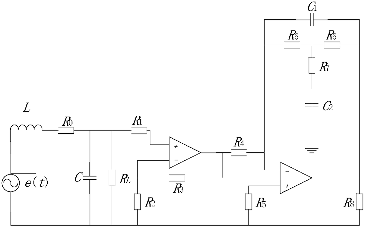
[0069] Embodiment 1: as figure 1 Shown, a kind of electronic current transformer based on Rogowski coil, comprises Rogowski coil equivalent circuit, amplifying circuit and integration circuit; Integration circuit is connected with Rogowski coil equivalent circuit through amplifying circuit; Said Rogowski coil equivalent circuit includes Induced electromotive force e(t), equivalent resistance R 0 , coil inductance L, coil equivalent stray capacitance C and sampling resistance R L ; Equivalent resistance R 0 , the coil inductance L and the coil equivalent stray capacitance C are connected in series on the induced electromotive force e(t), and the sampling resistance R L Connect in parallel to the equivalent stray capacitance C of the coil to obtain the sampling voltage u 1 (t); Described amplifying circuit comprises the first operational amplifier, resistance R1, resistance R2 and resistance R3; The same direction input end of the first operational amplifier is through resist...

Embodiment 2

[0071] Embodiment 2: A method for analyzing the characteristics of an electronic current transformer based on a Rogowski coil, the steps are as follows: S1, constructing a Rogowski coil equivalent circuit;

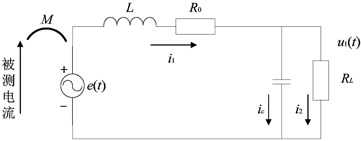
[0072] The Rogowski coil equivalent circuit, as figure 2 Shown, including induced electromotive force e(t), equivalent resistance R 0 , coil inductance L, coil equivalent stray capacitance C and sampling resistance R L ; Equivalent resistance R 0 , the coil inductance L and the coil equivalent stray capacitance C are connected in series on the induced electromotive force e(t), and the sampling resistance R L Connect in parallel to the equivalent stray capacitance C of the coil to obtain the sampling voltage u 1 (t).

[0073] S2, obtaining the transfer function of the Rogowski coil equivalent circuit;

[0074] S2.1, according to step S1, the voltage and current equation of the Rogowski coil equivalent circuit is obtained:

[0075]

[0076]

[0077]

[0078] ...


PUM


Abstract

The invention discloses an electronic current transformer based on a Rogowski coil. The electronic current transformer comprises a Rogowski coil equivalent circuit, an amplifying circuit and an integrating circuit. The integrating circuit is connected to the Rogowski coil equivalent circuit through the amplifying circuit. The Rogowski coil equivalent circuit in an established Rogowski coil electronic current transformer model is used for allowing coil parameters to be equivalent, and a voltage signal is outputted through a sampling resistor. The amplifying circuit amplifies a small voltage signal outputted from the coil to be used by subsequent integral components. A final integration circuit is the most important part, firstly, a good integration step can amplify a signal to be restored,the accuracy of measurement can be ensured, and errors are reduced. On the other hand, the signal can be optimized, and useless interference is filtered. The simulation is carried out according to theestablished Rogowski coil electronic current transformer model and the characteristics are analyzed, and technical support is provided for the electronic current transformer in the practical process.

Description

technical field [0001] The technical field of the current transformer of the present invention specifically relates to an electronic current transformer based on a Rogowski coil and a characteristic analysis method thereof. Background technique [0002] With the formation of the power grid pattern of "West-to-East Power Transmission, North-South Interconnection, and National Networking", my country's power system is developing rapidly in the direction of large capacity and high voltage. It is an important component in the relay protection system for tasks such as providing real and reliable electrical quantities for secondary equipment. With the continuous improvement of the grid voltage level and the increasing capacity of the power system, traditional electromagnetic current transformers have exposed disadvantages such as difficult insulation and insufficient linear operating range in actual operation, which cannot meet the requirements of intelligent and digital power syst...

Claims


Application Information

Patent Timeline
IPC IPC(8): G01R15/18G01R35/02
CPCG01R15/181G01R35/02
Inventor 叶远波吴迪陈实谢民王同文孙月琴程小平王薇郑浩汪胜和汪玉高博郑国强郝治国徐靖东张瀚文
Owner STATE GRID ANHUI ELECTRIC POWER
Why Eureka
Try Eureka