A scalable base station array, optical tracking system and tracking method thereof

An optical tracking and base station technology, applied in the field of base station arrays, can solve the problems of difficult to distinguish which base station the Y signal should belong to, error, and reduce the tracking accuracy of the tracking system, etc., to ensure large expansion, fast signal sorting, and high-efficiency optical The effect of tracking

Active Publication Date: 2020-08-11
BEIJING INSTITUTE OF TECHNOLOGYGY +1
View PDF11 Cites 0 Cited by
  • Summary
  • Abstract
  • Description
  • Claims
  • Application Information

AI Technical Summary

Problems solved by technology

[0013] However, considering that there may be some errors during assembly, the signal in the Y direction is bifurcated and becomes two scanning signals that are very close to each other.
When this kind of situation occurs, it will be difficult to distinguish which base station the Y signal should belong to, which will reduce the tracking accuracy of the tracking system to a certain extent

Method used


Image

  • A scalable base station array, optical tracking system and tracking method thereof
  • A scalable base station array, optical tracking system and tracking method thereof
  • A scalable base station array, optical tracking system and tracking method thereof

Examples


Embodiment 1

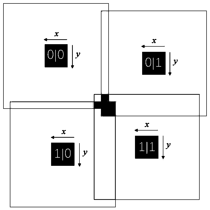
[0064] The present invention provides an expandable base station array, the layout structure of the array is as follows Figure 9 As shown, it is composed of m×n base stations in m rows and n columns. The scanning ranges of adjacent base stations overlap. When the base stations in the same row and the same row are arranged in a straight line, the positions of the base stations are the original positions.

[0065] The base stations whose rows and columns are both odd numbers or both even numbers are set at the original positions.

[0066] Base stations with different parity in the number of rows and columns are set at the offset set at the lower right of the original position. The offset is a preset value.

[0067] The set offset ensures that the scanning ranges of adjacent base stations overlap.

[0068] The minimum unit of the expandable base station array provided by the embodiment of the present invention is a unit array composed of 2 rows and 2 columns with a total of 4 ...

Embodiment 2

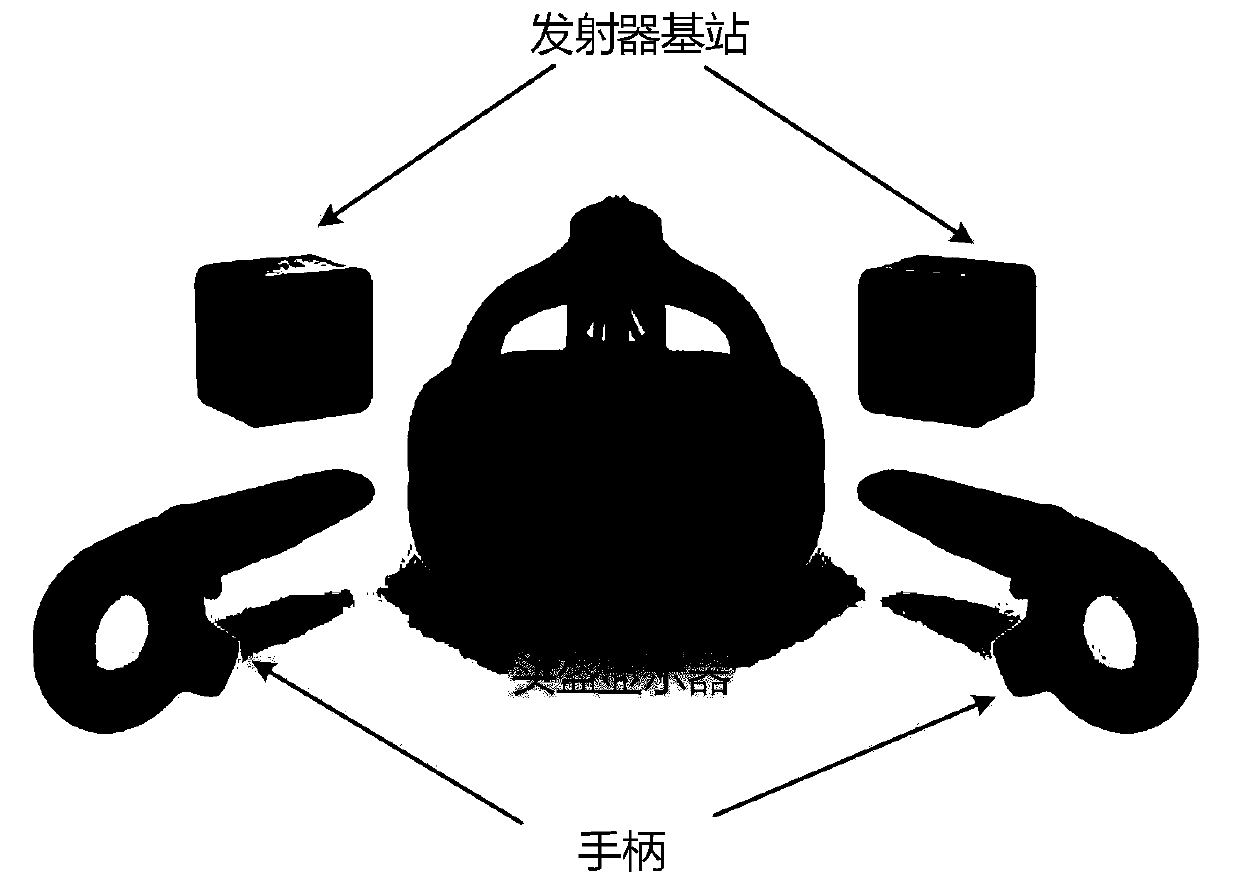
[0072] Based on the above-mentioned scalable base station array, the embodiment of the present invention proposes the following Figure 6 The optical tracking system shown includes an expandable base station array, a strobe, a receiver, a synchronization controller and a central processing unit; the system is used to track the target to be tracked.

[0073] The scalable base station array adopts the scalable base station array according to claim 1, the scalable base station array is parallel to the plane where the target to be tracked is located, and the scalable base station array is higher than the set height value of the plane where the target to be tracked is located.

[0074] Each base station in the expandable base station array corresponds to a strobe.

[0075] Each base station and its corresponding strobe in the scalable array of base stations is connected to a sync controller.

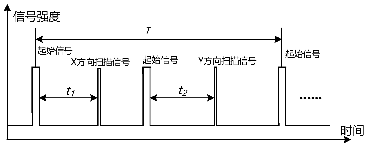
[0076] The synchronous controller controls the strobe to emit a start signal before the ...

Embodiment 3

[0080] For the above-mentioned optical tracking system based on the scalable base station array, the embodiment of the present invention also provides an optical tracking method based on the scalable base station array, the process of which is as follows Figure 5 As shown, the tracking method is used to track the target to be tracked;

[0081] S1. Set up a receiver on the target to be tracked;

[0082] S2. Use the strobe set at the set height to transmit the start signal and receive it by the receiver;

[0083] S3, using the expandable base station array as claimed in claim 1 arranged at a set height to scan the target to be tracked in the x direction first, and then scan in the y direction, and record the reception of the target to be tracked to the scanning signals in the x direction and the y direction time;

[0084] S4, judging that the target to be tracked corresponds to the base station when receiving the scanning signals in the x direction and the y direction;

[00...


PUM


Abstract

The invention discloses an expandable base station array, an optical tracking system and a tracking method thereof. The expansion of a base station is achieved, more accurate and fast signal sorting is achieved by preset offset layout, and thus more precise and efficient tracking system and tracking method are obtained. The technical solution of the present invention is that the expandable base station array is formed by m*n base stations in m rows and n columns, the scanning ranges of adjacent base stations overlap, and the position of each base station is an original position when the base stations in the same row and in the same column are in linear arrangement. A base station whose row number and column number are odd numbers or even numbers at the same time is arranged at an originalposition, and a base station whose row number and column number are an odd number and an even number is arranged at an offset position set at the lower right part of an original position. According toa set offset, the scanning ranges of the adjacent base stations overlap. For the base station array, the present invention provides the corresponding optical tracking system and tracking method.

Description

technical field [0001] The invention designs the technical field of optical tracking, and in particular relates to an expandable base station array, an optical tracking system and a tracking method thereof. Background technique [0002] HTC VIVE consists of a transmitter base station and a photosensitive receiver. The transmitter system can send out periodic light signals to scan the tracking area. After receiving the scanning signal from the transmitter, the receiver converts the light signal into a digital signal, so as to obtain the image coordinates of the receiver relative to the transmitter. When a certain number of After the receiver is scanned, the computer vision algorithm can be used to obtain the spatial pose of the rigid body composed of the receiver. [0003] The working principle of HTC VIVE is as follows: [0004] HTC VIVE's tracking system includes 2 transmitter base stations, 1 head-mounted display and 2 handles. There are dozens of photosensitive receive...

Claims


Application Information

Patent Timeline
Patent Type & Authority Patents(China)
IPC IPC(8): G01S5/16
CPCG01S5/16
Inventor 翁冬冬荀航李冬胡翔李跃
Owner BEIJING INSTITUTE OF TECHNOLOGYGY
Why Eureka
Try Eureka