
High-power LED heat dissipation structure based on thermoelectric refrigeration and micro-channel heat transfer

A technology of thermoelectric refrigeration and heat dissipation structure, which is applied in the direction of circuits, electrical components, semiconductor devices, etc., can solve the problems of low heat dissipation efficiency, reduce luminous flux, and affect the service life of LEDs, so as to improve work performance and reduce the temperature of the hot end, with good results Effect

Pending Publication Date: 2018-08-17
GUANGDONG UNIV OF TECH
View PDF0 Cites 4 Cited by
  • Summary
  • Abstract
  • Description
  • Claims
  • Application Information

AI Technical Summary

Problems solved by technology

However, the heat dissipation effect of some methods in the above-mentioned prior art is not obvious, and the heat dissipation efficiency is low, so that the light-emitting wavelength of the LED lamp deviates due to poor heat dissipation, reduces the luminous flux, and even affects the service life of the LED. These consequences restrict the LED from moving forward. greater power development
For high-power LED lamps or LED product illuminants, the above-mentioned existing air cooling or water cooling usually cannot meet the heat dissipation requirements

Method used


Image

  • High-power LED heat dissipation structure based on thermoelectric refrigeration and micro-channel heat transfer
  • High-power LED heat dissipation structure based on thermoelectric refrigeration and micro-channel heat transfer
  • High-power LED heat dissipation structure based on thermoelectric refrigeration and micro-channel heat transfer

Examples


Embodiment 1

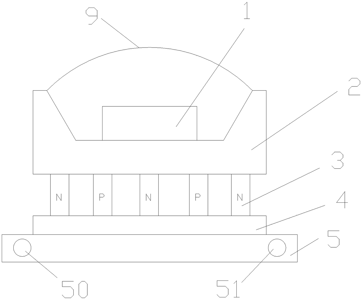
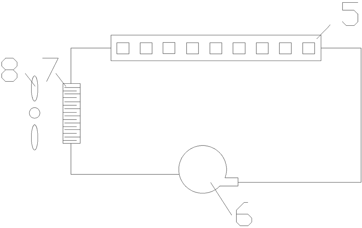
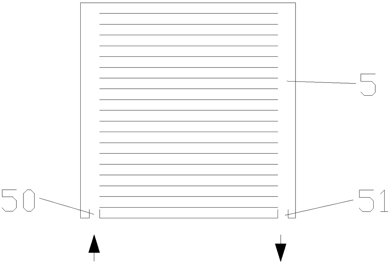
[0023] High-power LED cooling structure based on thermoelectric cooling and micro-channel heat transfer, such as figure 1 As shown, it includes a silicon substrate 2, an LED chip 1, a thermoelectric heat sink 4 and a microchannel heat exchanger 5. The LED chip 1 is attached to the cold end of the silicon substrate 2 to form an LED light source. The hot end of the silicon substrate 2 is connected to the cold end of the thermoelectric heat sink 4 , and the hot end of the thermoelectric heat sink 4 is connected to the cold end of the microchannel heat exchanger 5 . The LED chip 1 is connected to the silicon substrate 2 through soldering. Wherein the silicon substrate 2 and the thermoelectric heat sink 4 are integrally packaged, and the heat radiation end of the LED chip 1 is directly in contact with the thermoelectric heat sink 4 to improve heat dissipation efficiency. The thermoelectric heat sink 4 is fixedly connected with the microchannel heat exchanger 4 with crystal bonding...

Embodiment 2

[0030] High-power LED cooling structure based on thermoelectric cooling and micro-channel heat transfer, such as Figure 4-5 As shown, it includes an aluminum substrate 21 , an LED chip 2 , a thermoelectric heat sink 4 and a microchannel heat exchanger 5 . The LED chip 1 is mounted on the aluminum substrate 21 to form the LED light source part. The aluminum substrate 21 is attached to the cold end of the thermoelectric heat sink 4 , and the hot end of the thermoelectric heat sink 4 is connected to the cold end of the microchannel heat exchanger 5 . The nano-fluid working medium is used for heat exchange in the microchannel heat exchanger 5, and the nano-fluid working medium is exported to dissipate heat through an air-cooled or liquid-cooled radiator. An arc-shaped transparent cover 9 is mounted on the upper surface of the aluminum substrate 21 , and the transparent cover 9 encapsulates the LED chip 1 on the aluminum substrate 21 . A fluorescent powder layer is arranged insi...


PUM


Abstract

The invention discloses a high-power LED heat dissipation structure based on thermoelectric refrigeration and micro-channel heat transfer. The high-power LED heat dissipation structure comprises a substrate, an LED chip, a thermoelectric cooling fin and a micro-channel heat exchanger, wherein the LED chip is mounted on the substrate; the hot end of the substrate is connected to the cold end of thethermoelectric cooling fin, and the hot end of the thermoelectric cooling fin is connected to the cold end of the micro-channel heat exchanger. The high-power LED heat dissipation structure can significantly reduce the hot-end temperature of the thermoelectric cooling fin, so that the LED chip is directly cooled by the thermoelectric cooling fin. The high-power LED heat dissipation structure hasa good effect, and can improve the working performance, the reliability and the service life of the LED.

Description

technical field [0001] The invention relates to the technical field of LED heat dissipation, in particular to a high-power LED heat dissipation structure based on thermoelectric cooling and microchannel heat transfer. Background technique [0002] At present, the heat dissipation of LED lamps on the market mostly uses metal sheets or the heat generated by the substrate of the system is exported to the air for heat dissipation. The main methods adopted in the prior art are: rationally setting the structure of the heat sink to increase the heat dissipation area; using active cooling to dissipate heat or designing the package structure so that it has good luminous flux and effectively dissipates heat; or Is the use of water cooling, heat pipes and other methods. However, the heat dissipation effect of some methods in the above-mentioned prior art is not obvious, and the heat dissipation efficiency is low, so that the light-emitting wavelength of the LED lamp deviates due to po...

Claims


Application Information

Patent Timeline
Patent Type & Authority Applications(China)
IPC IPC(8): H01L33/64
CPCH01L33/645H01L33/648
Inventor 莫松平林潇晖陈颖贾莉斯
Owner GUANGDONG UNIV OF TECH
Learn More