Large-scale hydraulic generator collector ring connection structure and welding method

A technology for hydroelectric generators and connection structures, which is applied in the direction of motor generator connectors, high-frequency current welding equipment, connections, etc., and can solve the problem of shortening the life of the insulating layer on the surface of the connection structure of the slip ring and the high cross-sectional current density of the connection structure of the slip ring , the low mechanical strength of the confluence ring connection structure, etc., to achieve high reliability and economy, avoid virtual welding and missing welding, and shorten the welding heating time

Active Publication Date: 2018-08-17
CHINA YANGTZE POWER
View PDF4 Cites 0 Cited by
  • Summary
  • Abstract
  • Description
  • Claims
  • Application Information

AI Technical Summary

Problems solved by technology

The main disadvantages of this structure and method are: (1) When the interference fit between the confluence ring and the connecting pipe is to be connected, the internal air cannot be removed, and the solder cannot completely fill the gap between the confluence ring to be connected and the connecting pipe, resulting in virtual welding, Increase the contact resistance of the welding seam; (2) When the gap between the confluence ring to be connected and the connecting pipe is matched, the solder will leak along the fitting gap, forming burrs and sharp corners inside the confluence ring to be connected. During the operation of the generator High-energy partial discharge is generated, causing false alarms in the partial discharge monitoring system of the generator; (3) During the welding process, there is no temperature protection measure for the confluence ring to be connected, and the welding heat is conducted to the nearby main insulation layer through the pipe fittings, causing it to turn yellow when heated or blacken, the insulation performance of the main insulation is greatly reduced; (4) The mechanical strength of the connection structure of the slip ring is low, and the weld seam is prone to cracking due to long-term vibration; Shorten the life of the insulating layer on the surface of the bus ring connection structure

Method used


Image

  • Large-scale hydraulic generator collector ring connection structure and welding method
  • Large-scale hydraulic generator collector ring connection structure and welding method
  • Large-scale hydraulic generator collector ring connection structure and welding method

Examples


Embodiment Construction

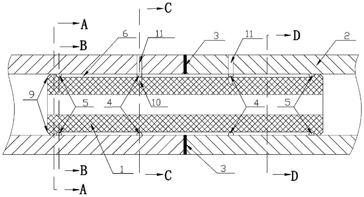
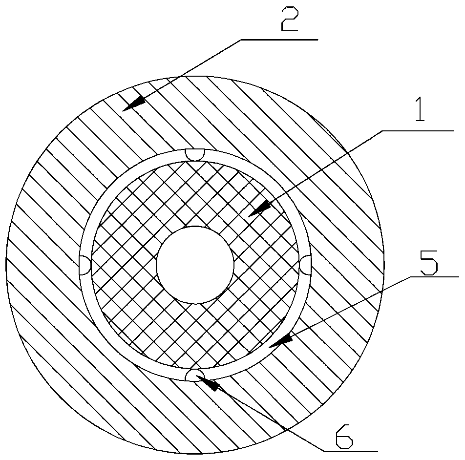
[0046] Such as Figure 1~6 Among them, a connection structure of a large hydro-generator collector ring, including a connecting pipe 1, the two ends of the connecting pipe 1 are respectively arranged in two collector rings 2 to be connected, the material of the connecting pipe 1 and the collector ring 2 to be connected is copper, An annular welding piece 3 is provided at the butt joint surfaces of the two confluence rings 2 to be connected, and the annular welding piece 3 is set on the connecting pipe 1, and both ends of the connecting pipe 1 are provided with a shaft collar 9, and the shaft collar 9 is symmetrical along the annular welding piece 3 distribution, the shaft collar 9 is in transition fit or interference fit with the collector ring 2 to be connected, and the outer end surface of the shaft collar 9 is chamfered, which is beneficial to the installation of the entire connecting pipe 1 .

[0047]The gap between the part of the connecting pipe 1 between the two shaft c...


PUM

PropertyMeasurementUnit
widthaaaaaaaaaa
depthaaaaaaaaaa
diameteraaaaaaaaaa

Abstract

The invention provides a large-scale hydraulic generator collector ring connection structure and a welding method, and the connection structure comprises a connection pipe. Two ends of the connectionpipe are respectively disposed in two to-be-connected collector rings, and the butt-joint surface of the two to-be-connected collector rings is provided with an annular soldering lug. The soldering lug sleeves the connection pipe, and two ends of the soldering lug are respectively provided with shaft collars. The shaft collars are in transition fit or interference fit with the to-be-connected collector rings. A part, located between the two shaft collars, of the connection pipe is in clearance fit with the to-be-connected collector rings. The to-be-connected collector rings are each provided with a material filling hole, and the material filling holes are disposed above a part, located between the two shaft collars, of the connection pipe. The welding method employs intermediate-frequencyinduction welding. The connection structure and the welding method enable soldering flux to be uniformly disposed in gaps between the collector rings and a connection part, prevent the soldering fluxfrom leaking to form burrs, enable the weld joints to be full and sturdy and are high in welding quality.

Description

technical field [0001] The invention relates to the field of large hydroelectric generator equipment, in particular to a connection structure and welding method for a collector ring of a large hydroelectric generator. Background technique [0002] The existing junction structure of hydro-generator slip rings is formed by installing connecting pipes inside the docking positions of the two slip rings to be connected, placing silver solder pieces at the seams, and intermediate frequency induction welding. The main disadvantages of this structure and method are: (1) When the interference fit between the confluence ring and the connecting pipe is to be connected, the internal air cannot be removed, and the solder cannot completely fill the gap between the confluence ring to be connected and the connecting pipe, resulting in virtual welding, Increase the contact resistance of the welding seam; (2) When the gap between the confluence ring to be connected and the connecting pipe is ...

Claims


Application Information

Patent Timeline
Patent Type & Authority Applications(China)
IPC IPC(8): H01R43/02B23K13/02
CPCB23K13/02H01R43/02H01R43/0263H01R2201/10
Inventor 陈锋
Owner CHINA YANGTZE POWER
Why Eureka
Try Eureka