
Bioretention facility

A bioretention and facility technology, applied in biological water/sewage treatment, granular microbial carrier treatment, water treatment parameter control, etc., can solve the problem of large fluctuation range of pollutant removal rate, unsatisfactory nitrogen and phosphorus removal effect, Filling soil is prone to clogging and other problems, so as to improve the rainwater infiltration capacity, facilitate growth, and improve the infiltration performance

Inactive Publication Date: 2018-08-21
GUANGZHOU EP ENVIROMENTAL ENG
View PDF3 Cites 2 Cited by
  • Summary
  • Abstract
  • Description
  • Claims
  • Application Information

AI Technical Summary

Problems solved by technology

However, due to the randomness and complexity of runoff water quality and water volume changes, the existing bioretention facilities have a large fluctuation range in the removal rate of pollutants in runoff rainwater, and the removal effect of nitrogen and phosphorus in runoff is not ideal, and the filling soil is easy Blockage occurs and the infiltration effect decreases, which restricts the use time of the facility, and the soil needs to be replaced after a short period of use

Method used


Image

  • Bioretention facility
  • Bioretention facility
  • Bioretention facility

Examples


Embodiment 1

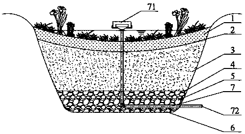
[0087] The volume of polyurethane biological ceramsite in the packing layer 3 of the present embodiment is 0.1cm 3 , the weight ratio of polyurethane biological ceramsite to filler matrix is ​​0.8%.

Embodiment 2

[0089] The volume of polyurethane biological ceramsite in the packing layer 3 of the present embodiment is 0.1cm 3 , the weight ratio of polyurethane biological ceramsite to filler matrix is ​​1.0%.

Embodiment 3

[0091] The volume of polyurethane biological ceramsite in the packing layer 3 of the present embodiment is 0.1cm 3 , the weight ratio of polyurethane bio-ceramsite to filler matrix is ​​1.5%.


PUM

PropertyMeasurementUnit
Volumeaaaaaaaaaa
Volumeaaaaaaaaaa
Volumeaaaaaaaaaa

Abstract

The invention discloses a bioretention facility. The bioretention facility comprises a planting soil layer, a first water permeable geotechnical cloth layer, a filling material layer, a second water permeable geotechnical cloth layer, and a drainage layer successively from top to bottom; the periphery and the bottom of the bioretention facility is provided with geotechnical cloth; the filling material layer comprises a filling material matrix, and polyurethane biological ceramsite; the filling material matrix is prepared via mixing of typha orientalis matrix soil with fine sand; the polyamidebiological ceramsite comprises a hollow biological ceramsite shell, and hydrophilic polyamide foam in the hollow biological ceramsite shell; the hollow biological ceramsite shell is provided with an opening used for exposure of at least a part of the hydrophilic polyamide foam. According to the filing material layer, the polyamide biological ceramsite is added into the filling material matrix composed of typha orientalis matrix soil and fine sand, so that the effective porosity of filling material layer is increased effectively, the percolation performance of the filling material layer is improved, filling material layer blocking is avoided effectively, rainwater percolation capability of the bioretention facility is improved, and blocking of the bioretention facility is avoided.

Description

technical field [0001] The invention relates to the technical field of sponge city rainwater treatment, and more specifically, relates to a biological retention facility. Background technique [0002] Bioretention facilities are an emerging low-impact development in-situ runoff rainwater control facility. They have good runoff pollution control effects, runoff volume reduction results, and peak flow control effects. They are economical and applicable, and can be widely used in urban greening. However, due to the randomness and complexity of runoff water quality and water volume changes, the removal rate of existing bioretention facilities for pollutants in runoff rainwater fluctuates widely, and the removal effect of nitrogen and phosphorus in runoff is not ideal, and the filling soil is easy to Blockage occurs, and the infiltration effect decreases, which restricts the service life of the facility, and the soil needs to be replaced after a short period of use. It is urgent...

Claims


Application Information

Patent Timeline
IPC IPC(8): C02F3/00C02F3/32C02F3/34
CPCC02F3/00C02F3/32C02F3/34C02F2003/001C02F2103/001C02F2209/08C02F2209/16C02F2209/18
Inventor 王文静阳重阳曹姝文李锐敬刘小平许嘉辉许佳敏
Owner GUANGZHOU EP ENVIROMENTAL ENG
Learn More