Integrated cooling separator and operating method thereof

A technology of cooling separation and separator, which is applied in the direction of combustible gas purification, combustible gas purification/transformation, gas dust removal, etc. It can solve the problems of unfavorable long-term operation of coal chemical plants, insufficient gas-liquid contact, low cooling and washing efficiency, etc., to achieve optimization Cooling and washing separation process, reducing equipment cost, and enhancing the effect of cooling and washing

Pending Publication Date: 2018-08-21
ACRE COKING & REFRACTORY ENG CONSULTING CORP DALIAN MCC
View PDF0 Cites 2 Cited by
  • Summary
  • Abstract
  • Description
  • Claims
  • Application Information

AI Technical Summary

Problems solved by technology

In the above-mentioned cooling and separation method, the cooling method of spraying the crude gas with circulating liquid is adopted, but in the actual application process, it is found that due to insufficient gas-liquid contact in the conventional washing cooler, the cooling and washing efficiency is low; the lower chamber of the waste heat boiler can only achieve preliminary The gas-liquid separation is relatively low, and the separation efficiency is also low; the circulating liquid and tar entrained in the crude gas are attached to the inner wall of the heat exchange tube, which greatly reduces the heat transfer coefficient and greatly increases the required heat exchange area.
The efficiency of cooling, washing, condensation, and separation in the above working process seriously affects the production cost, which is not conducive to the long-term operation of the coal chemical plant

Method used


Image

  • Integrated cooling separator and operating method thereof

Examples


Embodiment Construction

[0025] The specific embodiment of the present invention will be further described below in conjunction with accompanying drawing:

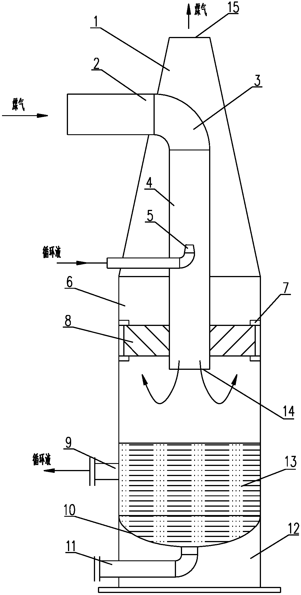
[0026] Such as figure 1 As shown, the integrated cooling separator of the present invention includes a separator body, a gas inlet pipe, a circulating liquid nozzle 5, a swirl plate demister 8 and a base 12; the separator body is arranged on the base 12, The separator body consists of a conical head 1, a cylinder 6 and an oval head 10 sequentially connected from top to bottom, the top of the conical head 1 is provided with a gas outlet 15, the oval head 10 and the lower part of the cylinder 6 There is circulating fluid at a set height, and the side wall of the cylinder 6 below the circulating fluid level is provided with a circulating fluid outlet 9, and the bottom of the oval head 10 is provided with a tar residue discharge port 11; the gas inlet pipe is connected by a horizontal pipe section 2 in sequence , a 90° elbow 3 and a vertical pipe sec...


PUM


Abstract

The invention relates to an integrated cooling separator and an operating method thereof. The integrated cooling separator comprises a separator body, a gas inlet pipe, a circulation liquid spraying pipe, a vortex plate demister and a base, wherein the separator body comprises a conical head, a cylinder and an ellipsoidal head; a gas outlet is formed in the top of a conical head; the gas inlet pipe comprises a horizontal pipe section, a 90-degree bend and a vertical pipe section; the circulation liquid spraying pipe extends into the vertical pipe section of the gas inlet pipe; a nozzle of thecirculation liquid spraying pipe is vertically upward in a liquid spraying direction; the vortex plate demister is arranged between the vertical pipe section of the gas inlet pipe and the side wall ofthe cylinder. The integrated cooling separator has the advantages that cooling, washing and separating technologies are integrated in one device, raw gas is cooled and washed in a mode of reverse impact of the raw gas and circulation liquid, and the contact area between the raw gas and circulation liquid is enlarged; a gas-liquid separation mode is improved according to a principle that centrifugal force and vapor liquid ratios are different, so that the cooling, washing and separating efficiency is improved, and the purpose of reducing the cost is achieved.

Description

technical field [0001] The invention relates to the technical field of high-temperature coal gasification, in particular to an integrated cooling separator for high-temperature coal gas and a working method thereof. Background technique [0002] In the coal pressurized gasification process, the temperature of the crude gas produced by coal gasification is very high. The current conventional cooling and separation method is as follows: first spray the circulating liquid in the washing cooler to cool the crude gas, and clean the entrained coal powder and impurities. . The crude gas coming from the washing cooler and carrying a large amount of circulating liquid enters the inlet pipe of the waste heat boiler. In the lower chamber, the oil and gas are separated, and the crude gas enters the heat exchange tube to exchange heat and condense with the water outside the tube. The lower chamber is an inverted cone for coarse separation of circulating fluid and tar. In the above-ment...

Claims


Application Information

Patent Timeline
Patent Type & Authority Applications(China)
IPC IPC(8): C10K1/02C10K1/04C10K1/08
CPCC10K1/02C10K1/026C10K1/046C10K1/08
Inventor 曲斌于涛段有龙
Owner ACRE COKING & REFRACTORY ENG CONSULTING CORP DALIAN MCC
Why Eureka
Try Eureka