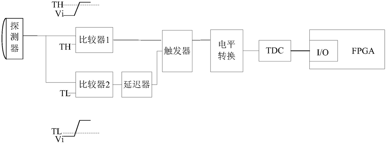
Detector timing device and detector
A timing device and detector technology, which is applied in measuring devices, instruments, scientific instruments, etc., can solve the problems of reducing the accuracy of time detection and large-scale circuits
- Summary
- Abstract
- Description
- Claims
- Application Information
AI Technical Summary
Problems solved by technology
Method used
Image
Examples
Embodiment 1
[0078] see Figure 5 , is a schematic structural diagram of a detector timing device provided by an embodiment of the present invention.
[0079] The detector timing device includes: a preamplifier 510 , a constant ratio circuit 520 and an FPGA530 .
[0080] The preamplifier 510, constant ratio circuit 520, and FPGA530 are connected sequentially, and the output signal of the detector is received by the preamplifier 510, and the output signal is sequentially processed by the preamplifier 510, constant ratio circuit 520 and FPGA530 to obtain the output of the detector The arrival time of the signal.
[0081] The preamplifier 510 is used to convert the output signal of the detector into a non-phase differential signal and an anti-phase differential signal.
[0082] In actual implementation, the preamplifier 510 can be a single-ended-to-differential amplifier, and of course, other devices that can convert a single-channel signal to a differential signal can also be used, as long...
Embodiment 2
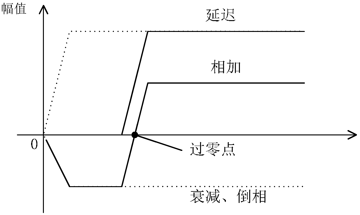
[0094] The timing principle of the detector will be described in detail below with reference to the accompanying drawings.
[0095] see Figure 6 , is a circuit diagram of a detector timing device provided by another embodiment of the present invention.
[0096] In this embodiment, the preamplifier 510 is a single-end-to-differential amplifier 601; the single-end-to-differential amplifier 601 is used to convert the signal output by the detector into two signals that are mutually differential. Specifically:
[0097] The first input terminal of the single-ended to differential amplifier 601 receives the output signal of the detector;
[0098] The second input terminal of the single-ended-to-differential amplifier 601 is grounded;
[0099] The first output terminal of the single-ended-to-differential amplifier 601 outputs a non-inverted differential signal +X, and the second output terminal of the preamplifier outputs an inverted differential signal -X.
[0100] In this embod...
Embodiment 3
[0149] The embodiment of the present invention also provides a detector, see Figure 10 , is the schematic diagram of the detector structure.
[0150] The detector includes a crystal 1020 and a photomultiplier tube 1030, and the above Figure 5 The detector timing device 1010 in;
[0151] Among them, the crystal 1010 is used to be hit by photons to generate visible light;
[0152] Photomultiplier tube 1020, used to sense visible light and generate photoelectron pulse signals;
[0153] The detector timing device 1030 is used to read the photoelectron pulse signal to obtain the time information of the annihilation event.
[0154] The above description is the working process of the detector in the PET system. For the specific implementation of the detector timing device, refer to the description in Embodiment 1, which will not be repeated here.
[0155] In the detector provided by the embodiment of the present invention, since the output signal of the detector is converted in...
PUM
 Abstract
Description
Claims
Application Information
 - R&D
- Intellectual Property
- Life Sciences
- Materials
- Tech Scout
- Unparalleled Data Quality
- Higher Quality Content
- 60% Fewer Hallucinations
Browse by: Latest US Patents, China's latest patents, Technical Efficacy Thesaurus, Application Domain, Technology Topic, Popular Technical Reports.
© 2025 PatSnap. All rights reserved.Legal|Privacy policy|Modern Slavery Act Transparency Statement|Sitemap|About US| Contact US: help@patsnap.com


