Movable splicing type 3D formation system adopting upper-side projection manner

A splicing and projection technology, applied in the field of 3D printing, can solve the problems of small printing device and limited processing size.

Pending Publication Date: 2018-08-24
GUANGZHOU HEIGE ZHIZAO INFORMATION TECH CO LTD
View PDF6 Cites 4 Cited by
  • Summary
  • Abstract
  • Description
  • Claims
  • Application Information

AI Technical Summary

Problems solved by technology

[0004] The disadvantage of this technology is that the printing devices are small, the processing size is limited, and it can only be used for printing small-volume items

Method used


Image

  • Movable splicing type 3D formation system adopting upper-side projection manner

Examples


Embodiment Construction

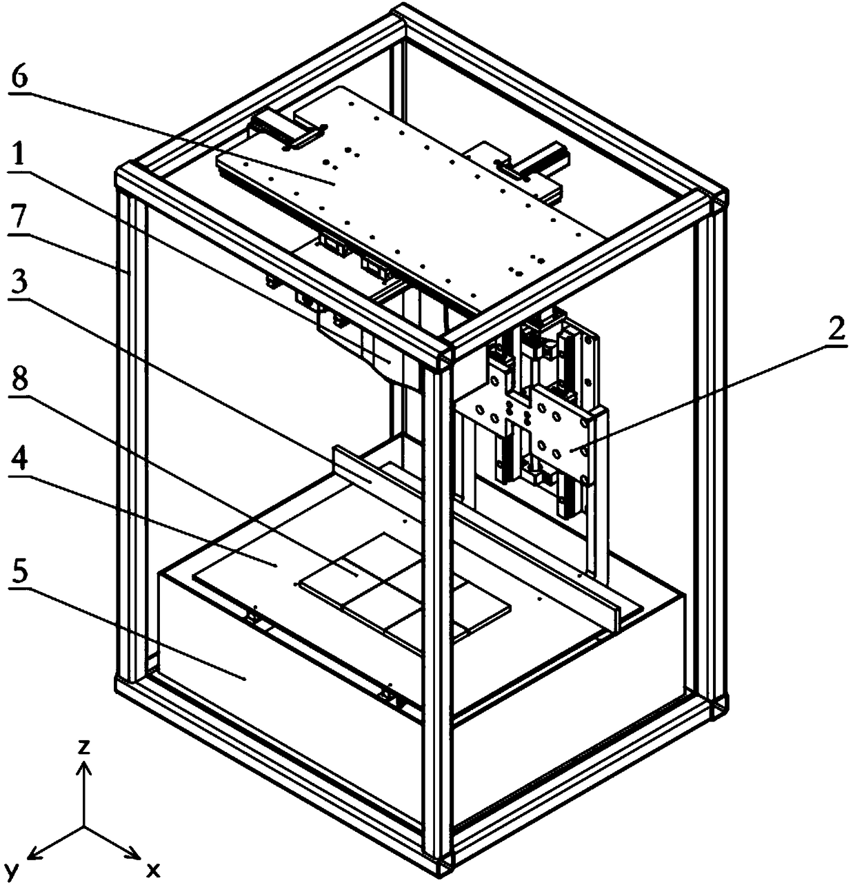
[0023] The present invention provides a 3D molding system in a mobile splicing and upward projection mode, which can print larger-sized items.

[0024] The following will clearly and completely describe the technical solutions in the embodiments of the present invention with reference to the accompanying drawings in the embodiments of the present invention. Obviously, the described embodiments are only some, not all, embodiments of the present invention. Based on the embodiments of the present invention, all other embodiments obtained by persons of ordinary skill in the art without making creative efforts belong to the protection scope of the present invention.

[0025] A 3D molding system of the mobile splicing upper projection mode of the present invention is:

[0026] a tray, the tray is used to hold the photocurable liquid;

[0027] A forming platform, the forming platform is located below the liquid surface of the photocurable liquid;

[0028] Lifting mechanism, the lif...


PUM


Abstract

The invention provides a movable splicing type 3D formation system adopting an upper-side projection manner. The movable splicing type 3D formation system adopting the upper-side projection manner canprint large-sized object and comprises a material disk, a forming platform, a lifting mechanism, a projector, an X-Y sliding platform assembly and a scraper blade. The material disk is used for containing photo-curing liquid. The lifting mechanism is connected with the forming platform and drives the forming platform to move up and down in the material disk. The X-Y sliding platform assembly is connected with the projector and drives the projector to transversely and longitudinally move on the upper side of the forming platform. The scraper blade is located above the material disk and horizontally moves relative to the material disk. The scraper blade is used for flattening the photo-curing liquid on the upper side of the curing layer on the forming platform in a scraping manner. Since the projector moves on the upper side of the material disk, when one layer is cured, the projector can move to a set position first of all, then begins exposure, achieves curing of one area, moves to anext position to continue to conduct exposure to cure a next area and the projector conducts curing in this way until complete exposure of the whole layer is achieved. After the whole layer is cured,the projector returns to the initial position, the lifting machine controls the forming platform to descend for the height equal to the thickness of one layer, and then printing of the large-sized object is completed.

Description

technical field [0001] The embodiments of the present invention relate to the technical field of 3D printing, and in particular to a 3D molding system of a moving splicing type and an upward projection method. Background technique [0002] DLP 3D printing technology mainly uses a projector to solidify photosensitive polymer liquid layer by layer to create 3D printed objects. The existing DLP 3D printing technology is printed by down projection. [0003] The printing principle of the existing down-projection DLP 3D printer is: the DLP device contains a liquid tank that can hold the resin, which is used to hold the resin that can be cured after being irradiated by ultraviolet light of a specific wavelength. The DLP imaging system is placed in the liquid tank. Below the tank, the imaging surface is just at the bottom of the tank. Through energy and graphics control, a thin layer of resin with a certain thickness and shape can be cured each time (this layer of resin is exactly ...

Claims


Application Information

Patent Timeline
Patent Type & Authority Applications(China)
IPC IPC(8): B29C64/124B29C64/20B29C64/255B29C64/214B33Y30/00
CPCB29C64/124B29C64/20B29C64/214B29C64/255B33Y30/00
Inventor 黄鹤源桂培炎罗铭
Owner GUANGZHOU HEIGE ZHIZAO INFORMATION TECH CO LTD
Why Eureka
Try Eureka