Full-efficiency combined air source heat pump system

An air source heat pump, combined technology, applied in heating systems, hot water central heating systems, energy-saving heating/cooling, etc. Cold source waste and other problems, to avoid energy efficiency decay or crash, reduce energy waste, and improve energy efficiency ratio

Pending Publication Date: 2018-08-24
高旭
View PDF7 Cites 1 Cited by
  • Summary
  • Abstract
  • Description
  • Claims
  • Application Information

AI Technical Summary

Problems solved by technology

However, from the perspective of practical application, even if an electric auxiliary heating device and a small-volume buffer water tank are installed, the heating effect is still not ideal in winter "rain, snow and fog" days, and the energy consumption is too large; "The impact of weather heating is particularly obvious; in order to prevent freezing of integral units, the usual method is to change the circulating water to circulating antifreeze, but in winter the system is troublesome to replenish antifreeze, which brings great inconvenience to users for maintenance.
[0005] 2. The existing air source heat pump (cold and warm water system) unit is used in constant temperature capillary cold radiation refrigeration in summer, because the design only has one liquid (refrigerant R410a or R22)-liquid (carrying refrigerant, such as water) heat exchange The system cannot realize the high-temperature refrigeration advocated by the industry, and the problem of system control "dew point" cannot be solved well, and the "dew point" control during cooling operation cannot be carried out; resulting in the system being applied to capillary cold radiation, cold radiation enclosure structures (such as walls Condensation on the surface, top surface) makes it difficult for the existing air source heat pump floor heating (cooling and heating) units to be applied to the advanced constant temperature capillary "no indoor unit" cold radiation refrigeration system
[0006] 3. In the existing air-cooled (that is, natural wind circulation) air source heat pump system, when cooling in summer, the waste heat generated by the outdoor main unit due to heat exchange and convection is not utilized, but most of it is directly discharged into the atmosphere, causing a certain amount of heat. The waste of waste, but also increased the ambient temperature of the surrounding atmosphere; winter heating, the outdoor host due to heat exchange and convection waste cooling is not used, but most of it is directly discharged into the atmosphere, resulting in waste of a certain cooling source, Reduced ambient air temperature
[0007] 4. In the existing air-cooled (that is, natural wind circulation) air source heat pump system, when the outdoor main engine is working in summer and winter, after the fan motor converts electrical energy into mechanical energy (that is, wind energy), the wind energy is not utilized, but directly discharged into the atmosphere , resulting in a certain waste of energy
[0008] 5. The existing air-cooled air source heat pump system has no design and configuration of heat (cold) recovery device due to design, process and other reasons. It has not been designed and considered to convert the electrical energy of the fan motor into mechanical energy once and then convert the mechanical energy into electrical energy for utilization. ;When the heat pump host is working, sometimes due to poor ventilation around the host, centralized installation of large-scale hosts, or outdoor atmospheric winds of 0-2 levels, the area around the host will be overheated in summer and too cold in winter, directly or indirectly affecting the working efficiency of the unit. Sometimes it may even cause the host to crash beyond the working condition range due to the surrounding environment of the host being too cold or overheating

Method used


Image

  • Full-efficiency combined air source heat pump system
  • Full-efficiency combined air source heat pump system

Examples


Embodiment Construction

[0038] The present invention will be described in further detail without limitation in conjunction with the accompanying drawings and examples below.

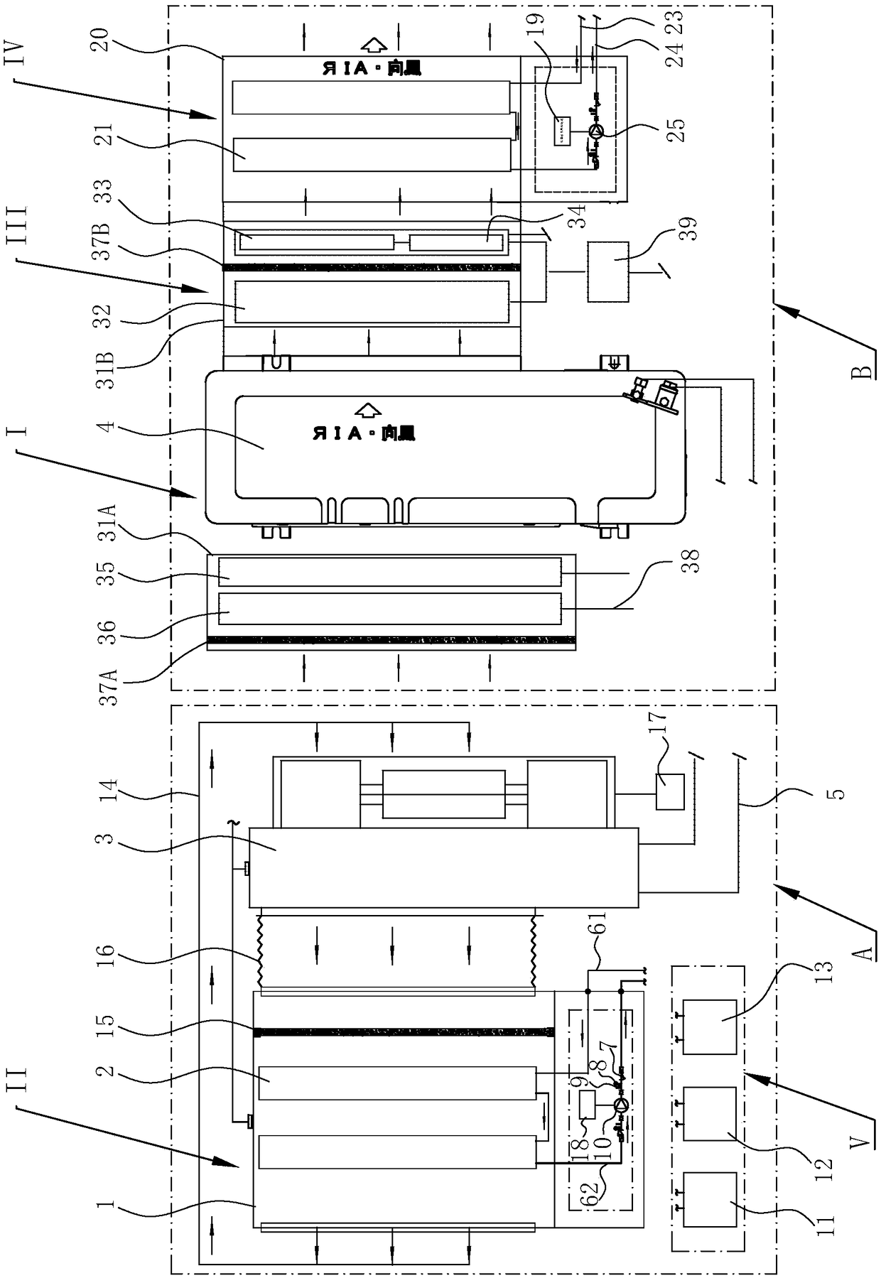
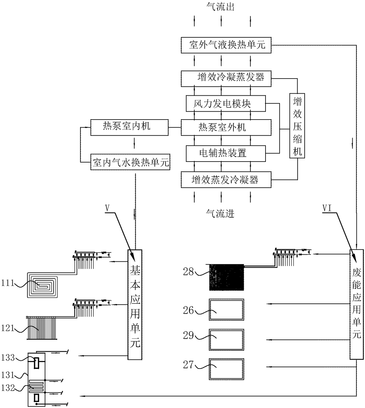
[0039] Such as figure 1 and figure 2 Commonly shown, the full-efficiency combined air source heat pump system of the present invention is divided into an indoor part A of the air source heat pump system and an outdoor part B of the air source heat pump system, including an air source heat pump unit I, an indoor air-water heat exchange unit II, an outdoor exhaust Wind efficiency unit III, outdoor gas-liquid heat exchange unit IV.

[0040] The air source heat pump unit 1 includes a heat pump controller 17 and a heat pump indoor unit 3 and a heat pump outdoor unit 4 connected through a refrigerant pipeline 5; the known heat pump indoor units have many different options, and can be frequency conversion multi-unit indoor units , or an indoor unit of an air-cooled modular unit, or a domestic and commercial one-to-one unit indoor u...


PUM


Abstract

The invention discloses a full-efficiency combined air source heat pump system, which comprises an air source heat pump unit, an indoor air-water heat exchange unit, an outdoor air exhaust synergisticunit, and an outdoor air-liquid heat exchange unit. The indoor air-water heat exchange unit is connected with an air outlet of a heat pump indoor unit; the output end of the indoor air-water heat exchange unit is connected with a basic application unit; the outdoor air exhaust synergistic unit which comprises a wind power generation module is arranged on the air outlet side of a heat pump outdoorunit; and the outdoor air-liquid heat exchange unit is connected with an air outlet of the outdoor air exhaust synergistic unit, and the output end of the outdoor air-liquid heat exchange unit is connected with a waste energy application unit. The problem of condensation in summer and the problem that frequent defrosting affects heating in winter are effectively solved; the fan wind energy of anoutdoor unit is converted into electric energy for recycling, and thus the energy waste is reduced; the waste cold and waste heat generated by the outdoor unit can be recycled, and thus the energy issaved and high efficiency is realized, emissions are reduced and the environment is protected; and the energy efficiency fading or crashing of a host machine due to supercooling or overheating in thesurrounding environment of the host machine is avoided, the stable and reliable operation of the unit is ensured and the multi-purpose of one machine is realized.

Description

technical field [0001] The invention relates to the technical field of air source heat pump central air conditioning, in particular to a full-efficiency combined air source heat pump system, which integrates various functions such as refrigeration, heating, hot water production, wind power generation, waste energy recovery and utilization, and energy storage. One. Background technique [0002] As a clean and environmentally friendly low-level heat source, air energy has the advantages of being inexhaustible, inexhaustible, available everywhere, and can be obtained free of charge, making air source heat pump units widely used in winter heating and summer cooling in households, enterprises and institutions. application. However, the air source heat pump units of the prior art still have the following problems to be solved urgently: [0003] 1. Due to the design and process of the existing air source heat pump (floor heating) unit system, when the system defrosts in winter (t...

Claims


Application Information

Patent Timeline
Patent Type & Authority Applications(China)
IPC IPC(8): F25B39/02F24D3/18
CPCF24D3/18F25B39/02Y02B30/12
Inventor 高旭
Owner 高旭
Why Eureka
Try Eureka