Automobile generator rotor assembling technology

An automobile generator and rotor assembly technology, which is applied in the manufacture of stator/rotor body, etc., can solve the problems of easy damage and cracking of fan blades and retaining rings, low knurling depth, and difficulty in pressing and fitting, so as to solve the problems of easy falling apart , Simple alignment, firm and stable assembly

Active Publication Date: 2018-08-24
江苏江南电机有限公司
View PDF9 Cites 2 Cited by
  • Summary
  • Abstract
  • Description
  • Claims
  • Application Information

AI Technical Summary

Problems solved by technology

[0007] In order to overcome the interference fit installation existing in the prior art, it is difficult to press and install, and the fan blade and retaining ring are easily damaged and cracked during installation; the knurling and teeth will wear out during long-term use, and the depth of knurling is generally Not deep, the surface of the rotor shaft will become smooth after wear, so that the fan blades will loosen or even fall off. The invention provides an assembly process for the rotor of an automobile generator, which is characterized in that it includes the following steps:

Method used


Image

  • Automobile generator rotor assembling technology
  • Automobile generator rotor assembling technology
  • Automobile generator rotor assembling technology

Examples


Embodiment Construction

[0032] The present invention will be described in further detail below in conjunction with the accompanying drawings and embodiments. It should be understood that the specific embodiments described here are only used to explain the present invention, not to limit the present invention.

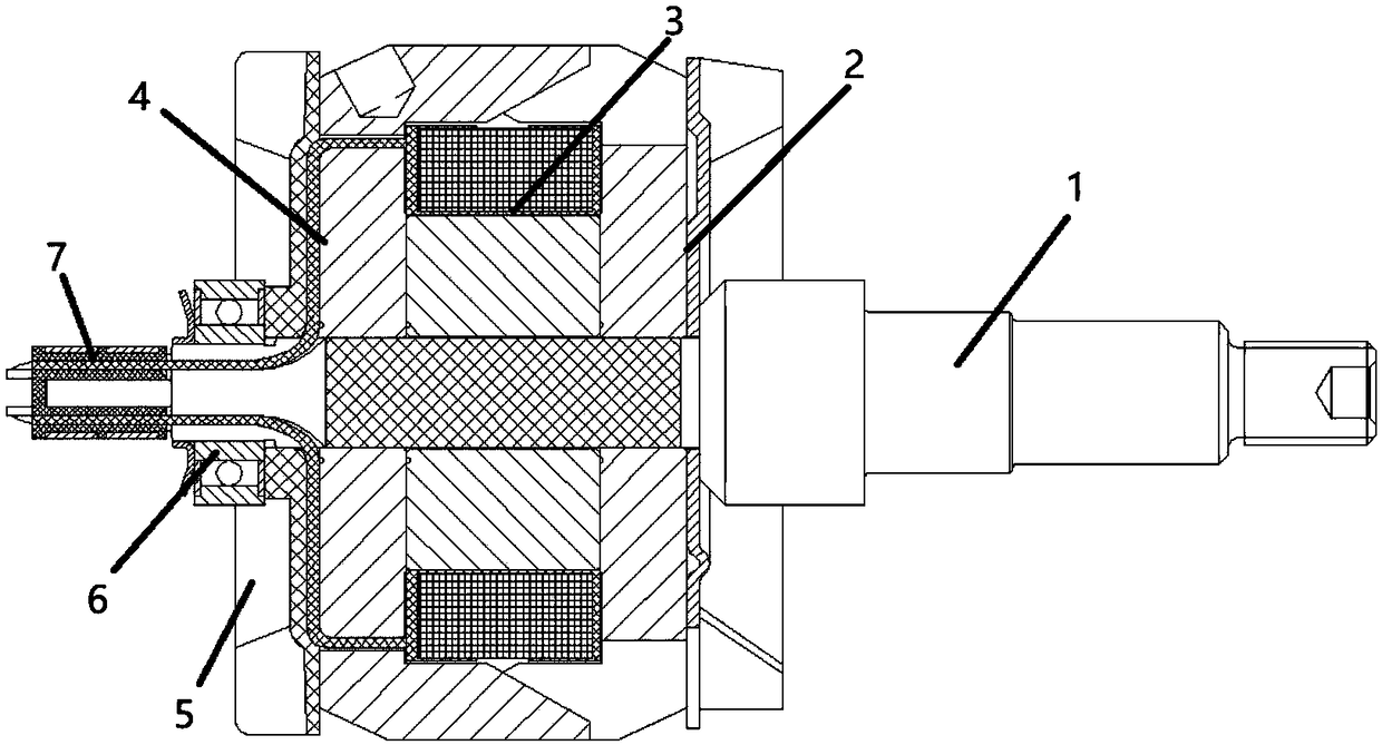
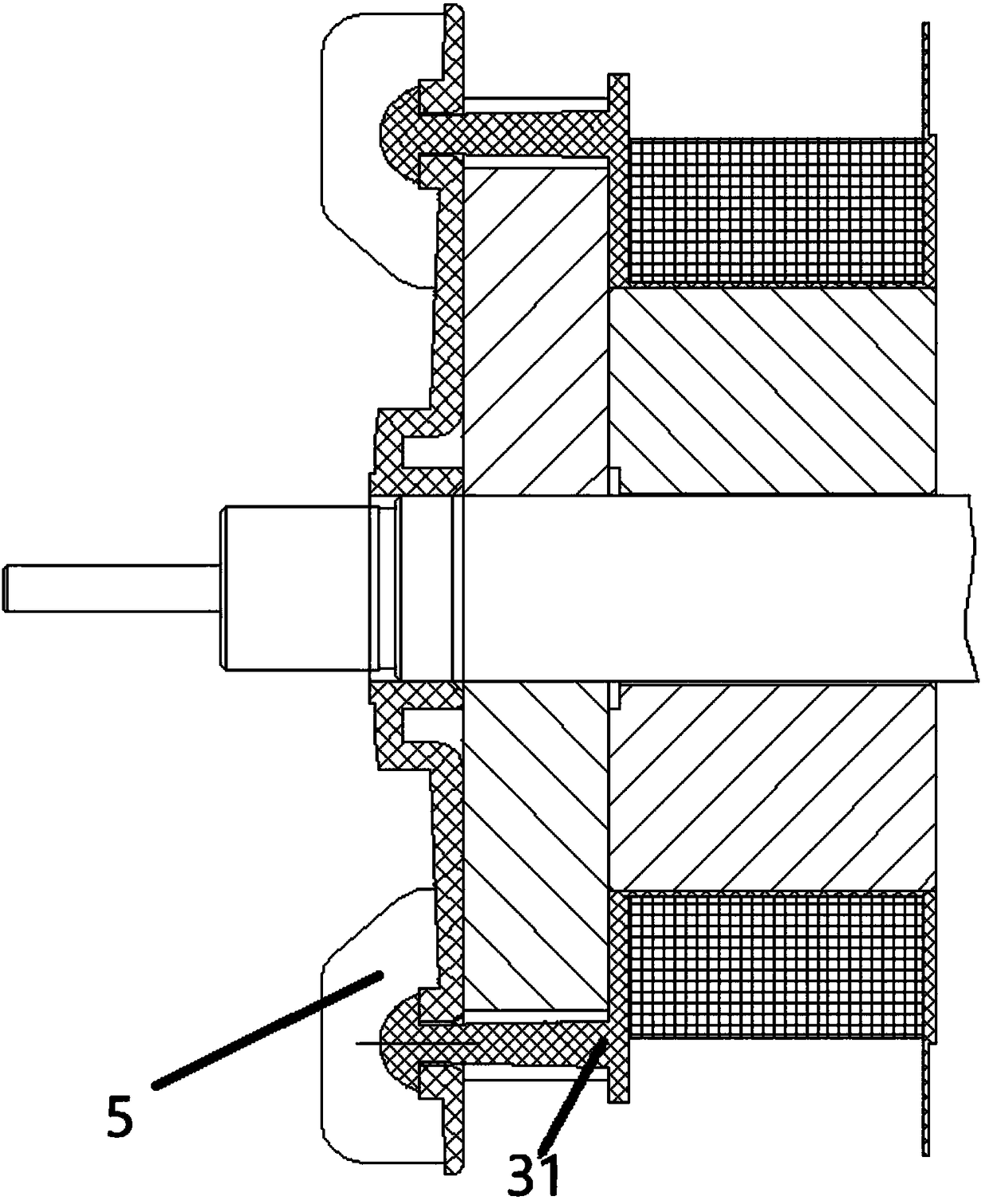
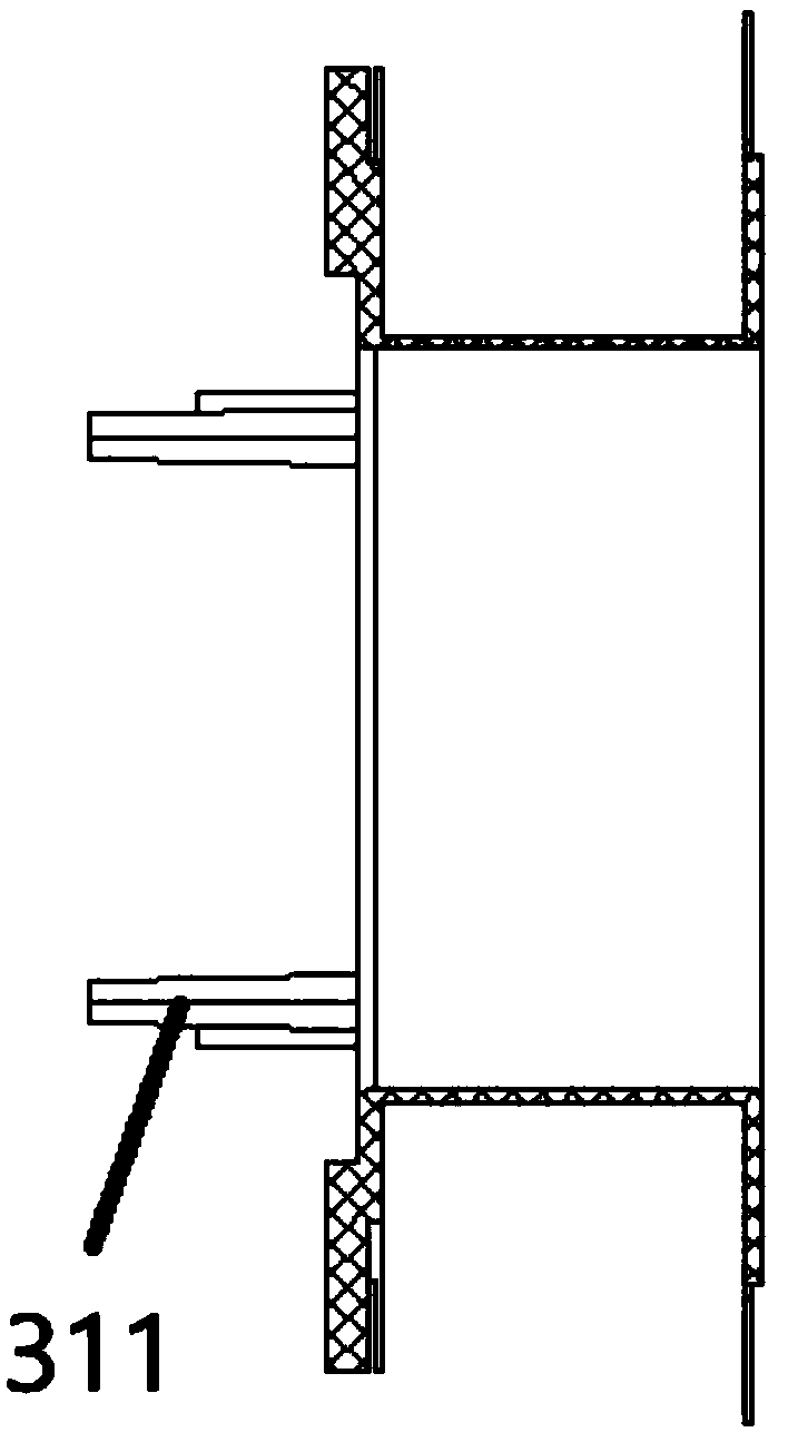
[0033] Such as Figure 1-Figure 4 As shown, the present invention schematically shows an assembly process of an automobile generator rotor.

[0034] The invention discloses an assembly process of an automobile generator rotor, which is characterized in that it comprises the following steps:

[0035] Step 1: Make an indenter according to the diameter of the rotor main shaft 1. Further, the shape of the indenter is tubular, the inner diameter of the indenter is larger than the outer diameter of the rotor main shaft 1, and one end is provided with an annular pointed boss. On the one hand, it avoids the interference between the rotor main shaft 1 and the indenter; on the other hand, it can effec...


PUM


Abstract

The invention provides an automobile generator rotor assembling technology which is characterized by comprising the following steps: step one: a pressure head is cooperatively manufactured according to the diameter size of a rotor spindle; step two: a right claw pole blade component is installed on the rotor spindle and then the right claw pole blade component is compressed on the rotor spindle byusing an oil press and the pressure head; step three: then an excitation coil winding component is installed on the rotor spindle and then the excitation coil winding component is compressed on the rotor spindle by using the oil press and the pressure head; step four: then a left claw pole is installed on the rotor spindle and then the left claw pole is compressed on the rotor spindle by using the oil press and the pressure head; step five: then left blades sleeve on the rotor spindle and the left blades are enabled to be aligned with the excitation coil winding component, and the left bladesand the excitation coil winding component are enabled to be welded and fixed through the ultrasonic welding technology; and step six: tin soldering of an outgoing line connector part is performed.

Description

technical field [0001] The invention relates to the technical field of generators, in particular to an assembly process of an automobile generator rotor. Background technique [0002] When the external circuit energizes the excitation winding through the brush, a magnetic field is generated to magnetize the claw poles into N poles and S poles. When the rotor rotates, the magnetic flux changes alternately in the stator winding. According to the principle of electromagnetic induction, an alternating induced electromotive force is generated in the three-phase winding of the stator. This is the power generation principle of the alternator. The rotor of the synchronous generator with DC excitation is driven by the prime mover (that is, the engine) to rotate at a speed of n (rpm), and the three-phase stator windings induce an AC potential. If the stator winding is connected to the electric load, the motor will have AC power output, and the rectifier bridge inside the generator wi...

Claims


Application Information

Patent Timeline
Patent Type & Authority Applications(China)
IPC IPC(8): H02K15/02
CPCH02K15/02
Inventor 梅一峰宋刚
Owner 江苏江南电机有限公司
Why Eureka
Try Eureka