
Loop heat pipe

A technology of loop heat pipe and road cover, which is applied in the direction of indirect heat exchangers, lighting and heating equipment, etc., can solve the problems of large system space occupation, cumbersome and complicated layout of loop heat pipe transmission pipelines, etc., and achieve small space occupation, convenient and flexible layout , the effect of simple appearance

Pending Publication Date: 2018-08-28
TECHNICAL INST OF PHYSICS & CHEMISTRY - CHINESE ACAD OF SCI
View PDF0 Cites 3 Cited by
  • Summary
  • Abstract
  • Description
  • Claims
  • Application Information

AI Technical Summary

Problems solved by technology

[0006] The purpose of the present invention is to provide a loop heat pipe to solve the problem of complicated and complicated layout of the transmission pipeline of the existing loop heat pipe and large space occupation of the system

Method used


Image

  • Loop heat pipe
  • Loop heat pipe
  • Loop heat pipe

Examples


Embodiment 1

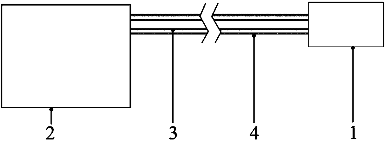
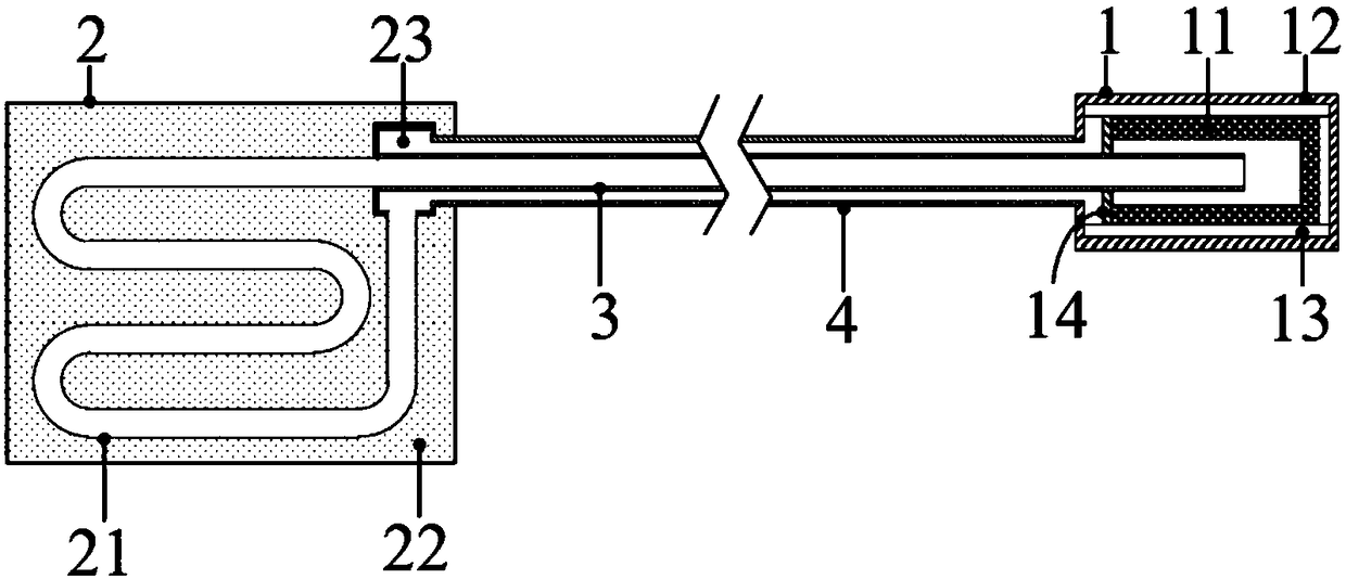
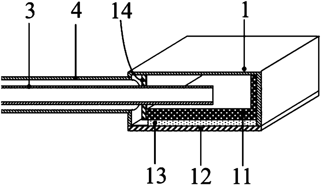
[0028] Such as Figure 1 to Figure 3 As shown, the embodiment of the present invention provides a loop heat pipe, including an evaporator 1, a condenser 2, and a transmission pipeline for connecting the evaporator 1 and the condenser 2 to form a loop. The transmission pipeline includes a gas pipeline 4 and a liquid pipeline 3, the gas pipeline 4 is set in the liquid pipeline 3 or the liquid pipeline 3 is set in the gas pipeline 4. In this embodiment, the liquid pipeline 3 is set in the gas pipeline 4 to form a pipe sleeve In the transmission pipeline of pipe structure, the inlet of the gas pipeline 4 and the outlet of the liquid pipeline 3 are connected to the evaporator 1 , and the outlet of the gas pipeline 4 and the inlet of the liquid pipeline 3 are connected to the condenser 2 .

[0029] Further, the external shape of the evaporator 1 can be cylindrical, disc-shaped, flat or saddle-shaped, or in the form of a pipeline, and the inside of the evaporator 1 can be a cavity, o...

Embodiment 2

[0040] Such as Figure 4 As shown, this embodiment is basically the same as Embodiment 1. For the sake of brevity, in the description process of this embodiment, the same technical features as Embodiment 1 will not be described, and only the differences between this embodiment and Embodiment 1 will be described. at:

[0041] This embodiment also includes a gas storehouse 41, the gas pipeline 4 is connected to the gas storehouse 41 through a bypass pipeline, and when the loop heat pipe works in a low-temperature temperature zone, it can effectively prevent the internal pressure of the loop heat pipe from exceeding the safe range at room temperature, and at the same time When the loop heat pipe is running at low temperature, the gas working medium in the gas storage 41 can be continuously replenished into the loop heat pipe, so as to ensure that there is sufficient gas-liquid two-phase working medium in the loop heat pipe, through continuous phase change and circulation of the g...


PUM


Abstract

The invention relates to the field of heat transferring equipment and discloses a loop heat pipe. The loop heat pipe comprises an evaporator, a condenser and a transmission pipeline used for connecting the evaporator and the condenser to form a loop, wherein the transmission pipeline comprises a gas pipeline and a liquid pipeline; the gas pipeline is sleeved in the liquid pipeline or the liquid pipeline is sleeved in the gas pipeline; the gas pipeline and the liquid pipeline of the transmission pipeline are arranged as structures formed by sleeving pipes with pipes; the gas pipeline and the liquid pipeline of the transmission pipeline are connected with the condenser and the evaporator to form the loop; the loop heat pipe is simple in appearance, compact in structure and small in occupiedspace, and is capable of facilitating the flexible layout of the system; the structures formed by sleeving pipes with pipes are used, so that the outer pipeline is capable of forming effective heat insulation protection on the inner pipeline; the environmental heat leakage of the outside to the inner pipeline is reduced; the stability and the reliability of the operation of the loop heat pipe canbe improved.

Description

technical field [0001] The invention relates to the field of heat transfer equipment, in particular to a loop heat pipe. Background technique [0002] A heat pipe is a highly efficient heat transfer device, its heat transfer capacity is one or two orders of magnitude higher than that of metal, and it is called a thermal superconductor. The traditional heat pipe mainly includes a metal shell, capillary structure and working medium. The capillary structure is usually composed of channels or sintered porous structures, and is distributed along the entire length of the heat pipe. Although the structure is simple, the flexibility is poor. With a full capillary structure, the liquid flow resistance is relatively large, and the liquid and gas flow in opposite directions in the same space, and there is a problem of carrying, which affects the further improvement of the heat transfer capacity of the heat pipe. [0003] The loop heat pipe is a thermal control device that utilizes the...

Claims


Application Information

Patent Timeline
IPC IPC(8): F28D15/04
CPCF28D15/0266F28D15/043
Inventor 赵雅楠陈厚磊梁惊涛
Owner TECHNICAL INST OF PHYSICS & CHEMISTRY - CHINESE ACAD OF SCI
Learn More