
Method for Determination of Material Creep Parameters Using Creep Test of Small Specimen with Fastened Straight Rod

A creep test and small sample technology, applied in the direction of applying stable tension/pressure to test material strength, electrical digital data processing, special data processing applications, etc., can solve the problem of inaccurate determination of material creep parameters, etc., to achieve The effect of accurate creep parameters and good correlation

Active Publication Date: 2021-03-23
EAST CHINA UNIV OF SCI & TECH
View PDF6 Cites 0 Cited by
  • Summary
  • Abstract
  • Description
  • Claims
  • Application Information

AI Technical Summary

Problems solved by technology

[0007] The purpose of the present invention is to provide a method for determining the creep parameters of a material by using the creep test of a small sample of a fixed straight rod. The present invention can accurately determine the creep of the material by using different creep deformation theories for different deformation stages of the material. Variable parameters are used to solve the problem that the current creep parameters in the large deformation stage are determined by the beam bending theory with small deformation assumptions, which makes the determination of material creep parameters inaccurate.

Method used


Image

  • Method for Determination of Material Creep Parameters Using Creep Test of Small Specimen with Fastened Straight Rod
  • Method for Determination of Material Creep Parameters Using Creep Test of Small Specimen with Fastened Straight Rod
  • Method for Determination of Material Creep Parameters Using Creep Test of Small Specimen with Fastened Straight Rod

Examples


Embodiment

[0072] Embodiment: The material is A7N01 aluminum alloy, and the test temperature of the small straight rod sample fixedly supported is 380°C. The process of using the method of the present invention to determine the creep parameters of A7N01 aluminum alloy is as follows:

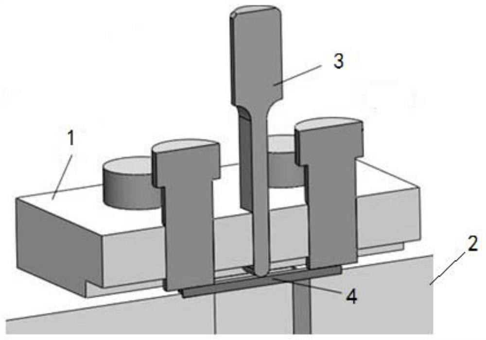
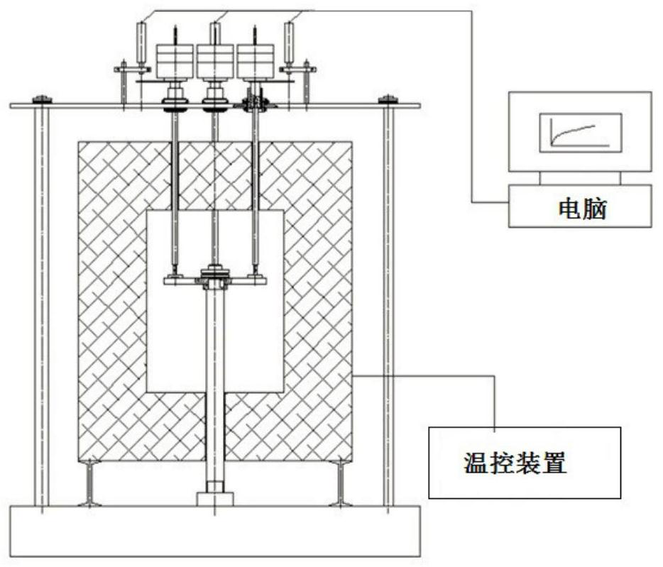
[0073] 1. Take materials from A7N01 aluminum alloy, and make a small straight rod sample of A7N01 aluminum alloy, such as figure 2 , fix the two ends of the small straight rod sample 4 with the upper mold 1 of the fixture, and press the lower end of the indenter 3 to press the middle area of ​​the straight rod small sample 4, and conduct creep tests on A7N01 aluminum alloy with different creep loads at 380°C , and after the test, obtain and record the creep displacement-time curve of the straight bar specimen, such as Figure 4 shown.

[0074] 2. Through the error function, combined with the size of the test device, it is determined that the critical displacement of the sample for small deformation and la...


PUM


Abstract

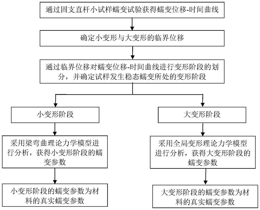
The invention relates to a method for determining the creep parameter of a material by a fixed straight bar small specimen creep test. The method comprises the following steps: (1) acquiring a fixed straight bar small specimen creep displacement time curve of the material; (2) determining critical displacements of small and large deformation of a specimen; (3) dividing deformation stages on the creep displacement time curve to determine the deformation stage of steady-state creep; (4) when the steady-state creep appears in a small deformation stage, analyzing a creep displacement curve of thesmall deformation stage according to a beam bending theory to obtain the creep deformation parameter of the material; (5) when the steady-state creep appears in a large deformation stage, analyzing acreep displacement curve in the large deformation stage according to a global deformation theory to obtain the creep deformation parameter of the material. By analyzing the fixed straight bar small specimen creep displacement time curve in stages, the true creep parameter of the material can be obtained more accurately.

Description

technical field [0001] The invention relates to material creep, in particular to a method for determining material creep parameters by using a fixed-supported straight bar small sample creep test. Background technique [0002] Creep, also called creep, is the tendency of a solid material to slowly and permanently move or deform under the influence of stress. It occurs as a result of prolonged stress below the yield strength of the material. Creep will be more severe when the material is heated for a long time or near the melting point. Creep often increases with increasing temperature. The rate of this deformation is related to material properties, loading time, loading temperature and loading structural stress. [0003] In the chemical process and power generation industries, in order to obtain high energy utilization, the working temperature and working pressure of equipment and components are constantly increasing, and the working environment is becoming more and more ...

Claims


Application Information

Patent Timeline
Patent Type & Authority Patents(China)
IPC IPC(8): G01N3/08G06F30/20G06F119/14
CPCG01N3/08G06F30/20G06F2119/06
Inventor 周帼彦秦宏宇王俊崎涂善东余海洋
Owner EAST CHINA UNIV OF SCI & TECH
Learn More