[0063] In order to make the features and advantages of this patent more obvious and understandable, the following specific examples are given to illustrate in detail as follows:
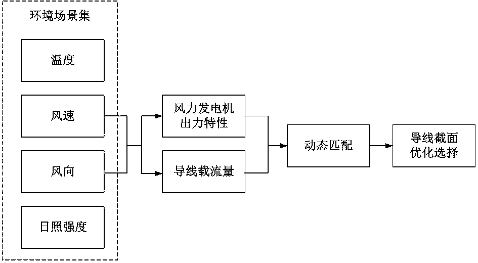
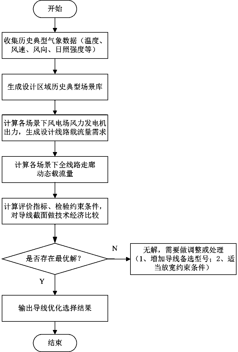
[0064] Such as figure 1 , image 3 As shown, this implementation method includes the following steps: including the following steps:
[0065] Step 1: Collect historical typical weather data, and generate a historical typical scene library (scene collection) of the design area;
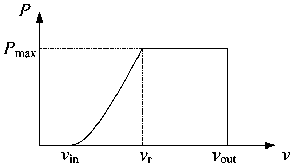
[0066] Step 2: Calculate the wind power output of the wind farm in each scenario, and simulate the processing curve. According to the typical wind speed time-space scenario of the wind farm generated in Step 1 and the wind power output characteristics of the wind power site configuration model, the wind power generation in the wind farm is obtained The output curve of the unit cluster in each typical scenario generates the current carrying capacity demand of the design line;
[0067] Step 3: According to the collected meteorological environmental parameters, calculate and generate the long-term allowable current carrying capacity of the conductors in each scenario under different environmental parameters;
[0068] Step 4: Optimize the selection of wires, calculate evaluation indicators, check constraints, compare different candidate types of wires in technology and economy, and judge whether there is an optimal choice; if there is an optimal choice, select the optimal wire, such as If there is no optimal choice, go to step 5;
[0069] Step 5: Add alternative wire types or relax the constraints, and perform step 4 again.
[0070] In this embodiment, the historical typical weather data in step 1 is generated based on historical temperature, wind speed, wind direction, and sunshine intensity data at the meteorological grid point (the grid size is selected according to needs, such as 5km×5km) where the wind farm and related transmission lines are located , Considering the typical historical scenarios of time dimension and space dimension at the same time.
[0071] In step 2, according to the historical typical scenarios generated in step 1, the output characteristics of wind turbines and calculation formulas are compared to calculate and generate the output of wind turbines in the wind farm in each typical scenario, and the design line of the wind farm under full load in each scenario is generated The current-carrying capacity demand, among which, the calculation of the wind power generation of the wind farm is based on the following formula:
[0072]
[0073] Where: v is wind speed; v in Is the cut-in wind speed of the wind turbine; v r The rated power wind speed of the wind turbine; v out Is the cut-out wind speed of the wind turbine; f(v) is the wind speed at v in To v r In between, the function of the relationship between the output power of the wind turbine and the wind speed, that is, the output characteristic, which can be expressed by a linear function and a halo function.
[0074] In step 3, the current carrying capacity of the conductor is calculated according to the following formula:
[0075]
[0076] Where: Q r Heat dissipation for radiation; Q c Heat dissipation for convection; Q s It is the solar radiation heat absorption; when the wire type is determined, ζ and τ are constant; R d It is DC resistance.
[0077] The basis for obtaining the above formula is:
[0078] According to the international methods used to calculate the maximum allowable current-carrying capacity of overhead conductors, the main IEEE standards (ie IEEE Standard for Calculating the Current-Temperature of Bare Overhead Conductors (IEEE 738-2006) and CIGRE standard (ie Mathematical Model for Evaluation of Conductor Temperature in The Steady (orQuasi-Steady) State (Normal Operation)), combined with the actual characteristics of China's line operation, according to the "110kV~750kV Overhead Transmission Line Design Specification" (GB 50545-2010), the calculation methods often used in the current design mainly refer to According to IEEE 738-2006 standard, the thermal balance equation of overhead wires can be expressed as the following form:
[0079]
[0080] Where: Q r Heat dissipation for radiation; Q c Heat dissipation for convection; Q s Is the solar radiation heat absorption; m is the quality of the wire; C p Is the specific heat capacity of the wire; T c Is wire temperature; I is wire carrying capacity; R T It is AC resistance.
[0081] Among them, radiation heat Q r The calculation method is as follows:
[0082] Q r =π·σ·D·k e ((T c +273) 4 -(T a +273) 4 )
[0083] In the formula: σ is the Stefan-Boltzmann constant, which is 5.67×10 -8 W/(m 2 K 4 ); D is the outer diameter of the wire; k e Is the radiation coefficient of the wire surface, the new wire is 0.23 ~ 0.43, and the old wire is 0.9 ~ 0.95.
[0084] Convection cooling Q c The calculation method is as follows:
[0085] Q c =π·λ f ·N u (T c -T a )
[0086] Where: λ f Is the heat transfer coefficient of the air layer on the wire surface, usually 0.02585/(W/mK); N u Is Euler's number and its calculation formula is: R in the formula e Is the Reynolds number, the calculation formula is: R e =1.644×10 9 v ⊥ ·D[T a +273+0.5(T c -T a )] -1.78 , Where v ⊥ Is the wind speed of the vertical wire.
[0087] Sunshine radiation heat absorption Q s The calculation method is as follows:
[0088] Q s =a·J s ·D
[0089] In the formula: a is the heat absorption coefficient, the new line is 0.23~0.43, and the old line is 0.9~0.95; J s Is the sunshine intensity.
[0090] AC resistance R T Usually use DC resistance R d And the product of the AC and DC resistance ratio β, namely:
[0091] R T = Β·R d
[0092] When using the Morgan formula to calculate the current carrying capacity of the wire, the calculation of the AC/DC resistance ratio is more complicated and there are many influencing factors. The calculation is usually based on the experimental conclusion that "the ratio of the AC and DC resistance of the wire is nonlinear to the current" is calculated according to the following formula. T ,which is:
[0093] R T =ζ·I τ ·R d
[0094] When the wire type is determined, ζ and τ are constants.
[0095] According to the above formula, the calculation formula of conductor current carrying capacity can be expressed as the following form:
[0096]
[0097] When the heat exchange between the wire and the outside reaches or is close to a steady state, the temperature change of the wire is very small and can be ignored, that is At this time, the calculation formula of wire current carrying capacity can be expressed as the following form:
[0098]
[0099] The above formula is the calculation formula for the real-time current-carrying capacity of the wire under steady state.
[0100] In this embodiment, in step 4, the optimal selection of wires is carried out, evaluation indexes are calculated, constraint conditions are checked, and different candidate types of wires are compared in terms of technology and economy, and the specific method for judging whether there is an optimal choice is:
[0101] Step 41: In the power design stage, when calculating the allowable current carrying capacity of the conductor, in order to simplify the calculation process, the allowable temperature and sunshine intensity of the conductor can be set to fixed values. For example, the allowable temperature of the conductor is generally 70 ℃ or 80 ℃, and the sunshine intensity is taken as 1000, the dynamic value can also be taken based on the typical scene generated by historical weather data in the area where the wind farm and the conductor are located.
[0102] According to the "Electrical Primary Part of the Electrical Design Manual of Power Engineering", the selection and verification of the wire cross section can be selected according to the continuous working current of the loop, and can also be selected according to the economic current density. Considering that the economic current density curve and value in the design regulations are affected by changes in technical and economic aspects and limited by the use conditions, it can no longer meet the selection of economic cross-section of wind farm conductors. According to the specific ideas proposed in this embodiment, the conductor cross-section can be optimized The selection problem is expressed as the following optimization problem and model, and the objective function is set as:
[0103] minf=min(c inv +c loss )
[0104] Where: c inv Is the investment cost of the line; c loss Is the annual operating loss cost of the line project;
[0105] Among them, the investment cost of the line c inv Calculate as follows:
[0106] c inv =m·c j
[0107] Where: m is the calculation coefficient of net present value; c j The cost per unit length of the wire of type j;
[0108] The net present value calculation coefficient m is calculated as follows:
[0109]
[0110] Among them: r is the discount rate, usually 6% to 7%; y is the life cycle of the line project, the unit is: year.
[0111] Annual operating loss cost of line engineering c loss Calculate as follows:
[0112]
[0113] Among them: where: S represents the scene; T represents the total number of intraday periods; Is the actual current carrying capacity of the wire of type j at time t under scene S; R Tj,s,t Is the AC resistance value of the wire of type j at time t under scene S; L line Is the length of the line project; λ e The on-grid tariff for wind power;
[0114] The actual current carrying capacity of the wire is calculated as follows:
[0115]
[0116] Where: I s,t Is the current carrying capacity requirement of the wind farm's external power at time t under scenario S; I j,s,t Is the current-carrying capacity of the wire of type j at time t in scenario S;
[0117] Step 42: Set constraints. Constraints are mainly used to indicate that the output line project of the wind farm needs to meet the demand of clean energy consumption ratio, which can be specifically considered from the following aspects:
[0118] Probability constraint of line carrying capacity exceeding limit:
[0119] p(I s,t ≥I j,s,t )≤α
[0120] In the formula: α is the confidence level, and the typical values are 1%, 5% and 10%;
[0121] Level constraints on the lowest abandonment rate:
[0122]
[0123] Where: P j,s,t Indicates the power sent from the wind farm at time t under scenario S when the wire with the wire type j is selected; β is the required minimum abandonment rate level.
[0124] The above-mentioned optimization model can realize the optimal selection of the cross section of the overhead soft conductor of the wind farm. It is worth noting that in the actual application process of this embodiment, the wind speed and ambient temperature can be conservatively processed according to the safety requirements and the project scope, or the calculated dynamic ampacity value can be conservatively processed (for example, multiplied by a Scale factor), or a higher-level wire cross-section can be selected based on the results of the proposed method.
[0125] The following is a specific example to further illustrate the method for selecting the cross section of overhead flexible conductors for wind farms proposed in the present invention:
[0126] Take a wind farm and its output lines as an example. The wind farm has 80 wind turbines with a single rated capacity of 1500kW. The output characteristics are as follows: figure 2 Shown. Among them, the cut-in wind speed of the wind turbine v in 3m/s; rated power wind speed v r 10.5m/s; cut out wind speed v out It is 25m/s. The wind speed is between the cut-in wind speed and the rated wind speed, and the function of the relationship between the output power of the wind turbine and the wind speed is expressed by a linear function. Assuming that the output line voltage level of the wind farm is 110kV, such as Figure 4 Shown. There is one meteorological observation point (observation point A and observation point B in the figure) every 5 kilometers, and the line length is about 10km. In order to select the wires that match the output characteristics of the wind farm, according to the historical wind speed and temperature data ( Figure 5 to Figure 9 ), as well as the relevant parameters and reference cost of the wires in Table 1 to Table 3, wind power feed-in tariff λ e The value is 0.4 yuan/kwh. The historical wind speed is already the wind speed perpendicular to the line and the wind generator obtained after processing. The optimized selection results of the conductor cross-sections with different confidence levels α and different minimum wind abandonment rates obtained using the method proposed in this embodiment are shown in Table 4.
[0127] Table 1: Common LGJ type steel core aluminum stranded wire parameter values
[0128]
[0129] Table 2: Reference cost of common LGJ steel core aluminum stranded wire
[0130]
[0131] Table 3: Values of other calculation parameters of the wire
[0132]
[0133] Table 4: Optimal selection results of conductor cross section
[0134]
[0135] According to the results of the optimal selection of conductor cross-sections listed in Table 4, the conductor cross-section of the output line of the wind farm can be selected according to the needs. For example, under the requirement of the minimum abandonment rate of 1%, the optimal conductor model is LGJ-150/35. If the maximum current carrying capacity of the wire is set according to the wind speed of 0.5m/s and the ambient temperature of 40℃, even if the maximum cross-section LGJ-400/35 of the model to be selected is selected for the wire type of the output line, it cannot meet the requirements, and a larger wire cross-section is required. This also proves the economics of the method proposed in the embodiment of the present invention.
[0136] This patent is not limited to the above-mentioned best embodiments. Under the enlightenment of this patent, anyone can draw other various forms of wind farm overhead flexible conductor cross-section selection methods. All changes made in accordance with the scope of the patent application of the present invention are equivalent to Modifications should all fall within the scope of this patent.