Used lubricating oil recycling device

A technology of waste lubricating oil and the other side, applied in the field of waste lubricating oil recycling device, can solve the problems of promoting lubricating oil oxidation, polluting lubricating oil, human body and biological harm, etc., to achieve the effect of easy precipitation and convenient heat preservation

Pending Publication Date: 2018-08-31
东营市安凯石油化工有限公司
View PDF12 Cites 2 Cited by
  • Summary
  • Abstract
  • Description
  • Claims
  • Application Information

AI Technical Summary

Problems solved by technology

Lubricating oil will gradually age and deteriorate due to high temperature and air oxidation during use, coupled with metal powder from friction parts, moisture entering the oil due to respiration and other reasons, and impurities intruding from the environment , These not only pollute the lubricating oil, but also promote the oxidation of the lubricating oil, which may cause various failures of the machine. Therefore, the lubricating oil must be replaced after it has been used for a certain period of time and has deteriorated to a certain extent. Many lubricating oils are added with heavy metal salt additives, and some are added with chlorine-containing organic compounds, sulfur-containing organic compounds, phosphorus-containing organic compounds, sulfur- and phosphorus-containing organic compounds, and some chlorine-containing compounds are more Chlorine substitutes for aromatic hydrocarbons. These compounds containing heavy metals, sulfur, phosphorus, and chlorine are toxic substances, harmful to humans and organisms, and may harm humans through various channels. Oil entering the water system has a strong pollution effect on water. , therefore, it is necessary to invent a waste lubricating oil recycling device to solve the above problems

Method used


Image

  • Used lubricating oil recycling device
  • Used lubricating oil recycling device
  • Used lubricating oil recycling device

Examples


Embodiment Construction

[0014] The following will clearly and completely describe the technical solutions in the embodiments of the present invention with reference to the accompanying drawings in the embodiments of the present invention. Obviously, the described embodiments are only some, not all, embodiments of the present invention. Based on the embodiments of the present invention, all other embodiments obtained by persons of ordinary skill in the art without making creative efforts belong to the protection scope of the present invention.

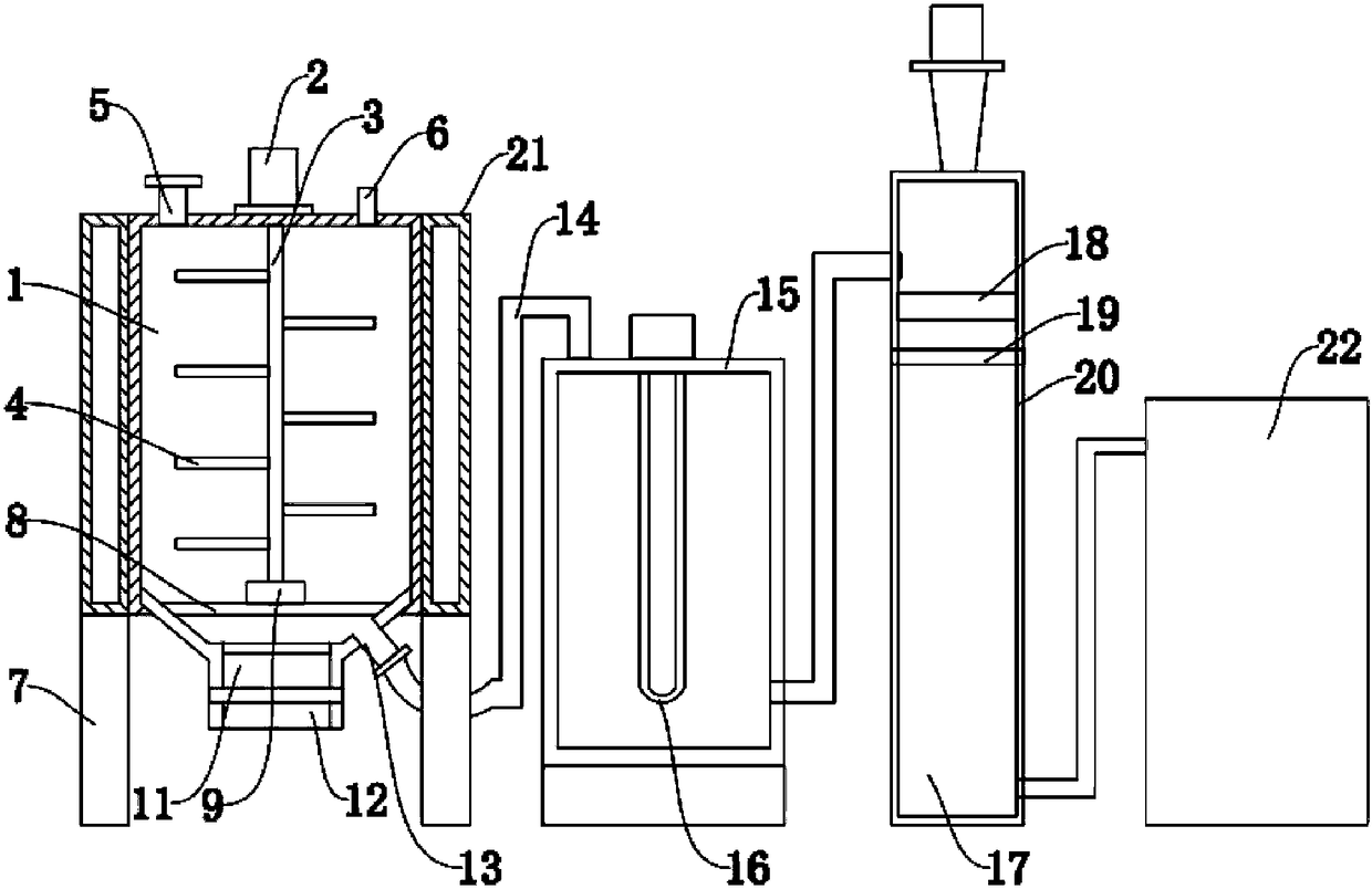
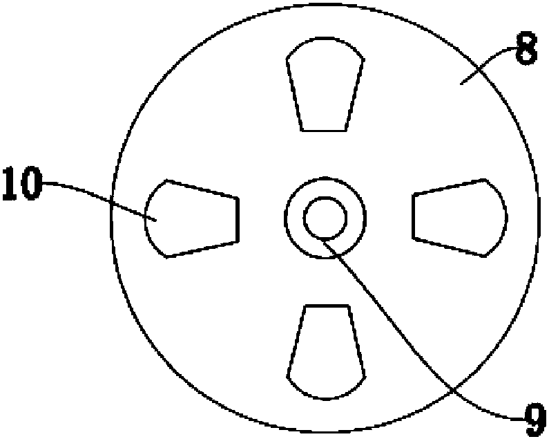
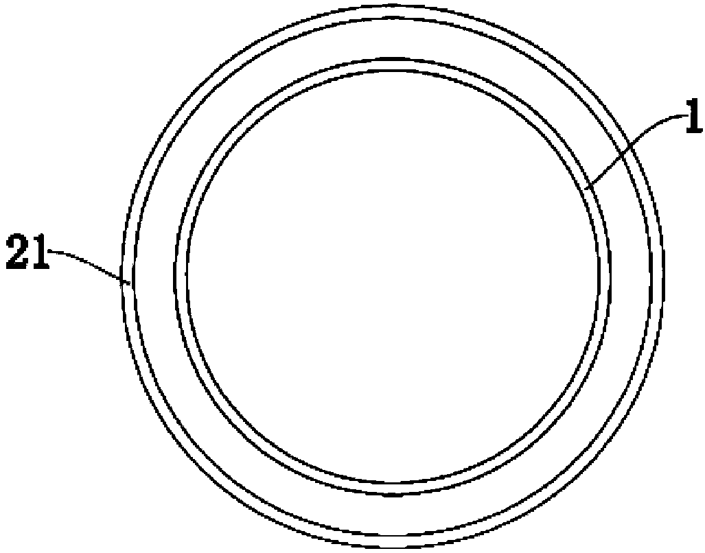
[0015] see Figure 1-3 , a waste lubricating oil recycling device, comprising a tank body 1, a first motor 2 is installed above the tank body 1, a stirring rod 3 is connected to the output end of the first motor 2, and the stirring rod 3 Through the upper wall of the tank body 1, and the stirring rod 3 extends to the inside of the tank body 1, the outer side of the tank body 1 is sealed and welded with an outer casing 21, and a vacuum layer is arranged between...


PUM


Abstract

The invention discloses a used lubricating oil recycling device. The device comprises a tank, wherein a first motor is mounted above the tank, a stirring rod is connected to an output end of the firstmotor, a casing is welded to the outer side of the tank in a sealed manner, a vacuum layer is arranged between the casing and the tank, a filter box is connected below the tank, a support plate is welded fixedly above the filter box, openings are formed in the support plate, a bearing block is fixedly connected to the middle above the support plate, an emptying port is connected below the conicalfilter box, the filter box is connected with an oil outlet in one side of the emptying port, the other end of the oil outlet is connected with an intermediate box through a connecting pipe, the otherside of the intermediate box is connected with a film evaporator through a pipeline, and one side of the film evaporator is connected with an oil storage tank. The used lubricating oil recycling device is reasonable in design, recycling of used lubricating oil is convenient to realize, and the device is worth spreading.

Description

technical field [0001] The invention relates to the technical field of waste lubricating oil recycling devices, in particular to a waste lubricating oil recycling device. Background technique [0002] China's lubricating oil production accounts for about 2% of the total petroleum products, and the amount is more than 3 million barrels per year. Lubricating oil will gradually age and deteriorate due to high temperature and air oxidation during use, coupled with metal powder from friction parts, moisture entering the oil due to respiration and other reasons, and impurities intruding from the environment , These not only pollute the lubricating oil, but also promote the oxidation of the lubricating oil, which may cause various failures of the machine. Therefore, the lubricating oil must be replaced after it has been used for a certain period of time and has deteriorated to a certain extent. Many lubricating oils are added with heavy metal salt additives, and some are added wit...

Claims


Application Information

Patent Timeline
Patent Type & Authority Applications(China)
IPC IPC(8): B01D36/00B01D29/58B01D29/11B01D29/075B01D1/06B01D1/30C10M175/00
CPCB01D1/065B01D1/30B01D29/11B01D29/58B01D36/00C10M175/0083B01D29/075
Inventor 周凯李强李小栋
Owner 东营市安凯石油化工有限公司
Why Eureka
Try Eureka