Transceiver joint robust optimization method for improving MIMO-STAP worst detection performance

A robust optimization and error detection technology, applied to radio wave measurement systems, instruments, etc., can solve the problems of MIMO-STAP radar system performance degradation, sidelobe and clutter suppression problems are not considered

Active Publication Date: 2018-08-31
DALIAN UNIV
View PDF6 Cites 6 Cited by
  • Summary
  • Abstract
  • Description
  • Claims
  • Application Information

AI Technical Summary

Problems solved by technology

Therefore, the optimized waveform obtained by relying on these estimates is bound to be affected by estimation errors, resulting in the performance degradation of the MIMO-STAP radar system
In addition, the above detection algorithm does not consider sidelobe and clutter suppression, and suppressing sidelobe can not only concentrate the main energy in the main lobe area to improve the detection ability of the target, but also reduce clutter and false targets from the side lobe area energy of

Method used


Image

  • Transceiver joint robust optimization method for improving MIMO-STAP worst detection performance
  • Transceiver joint robust optimization method for improving MIMO-STAP worst detection performance
  • Transceiver joint robust optimization method for improving MIMO-STAP worst detection performance

Examples


Embodiment Construction

[0116] The present invention will be further described below in conjunction with the accompanying drawings and specific embodiments.

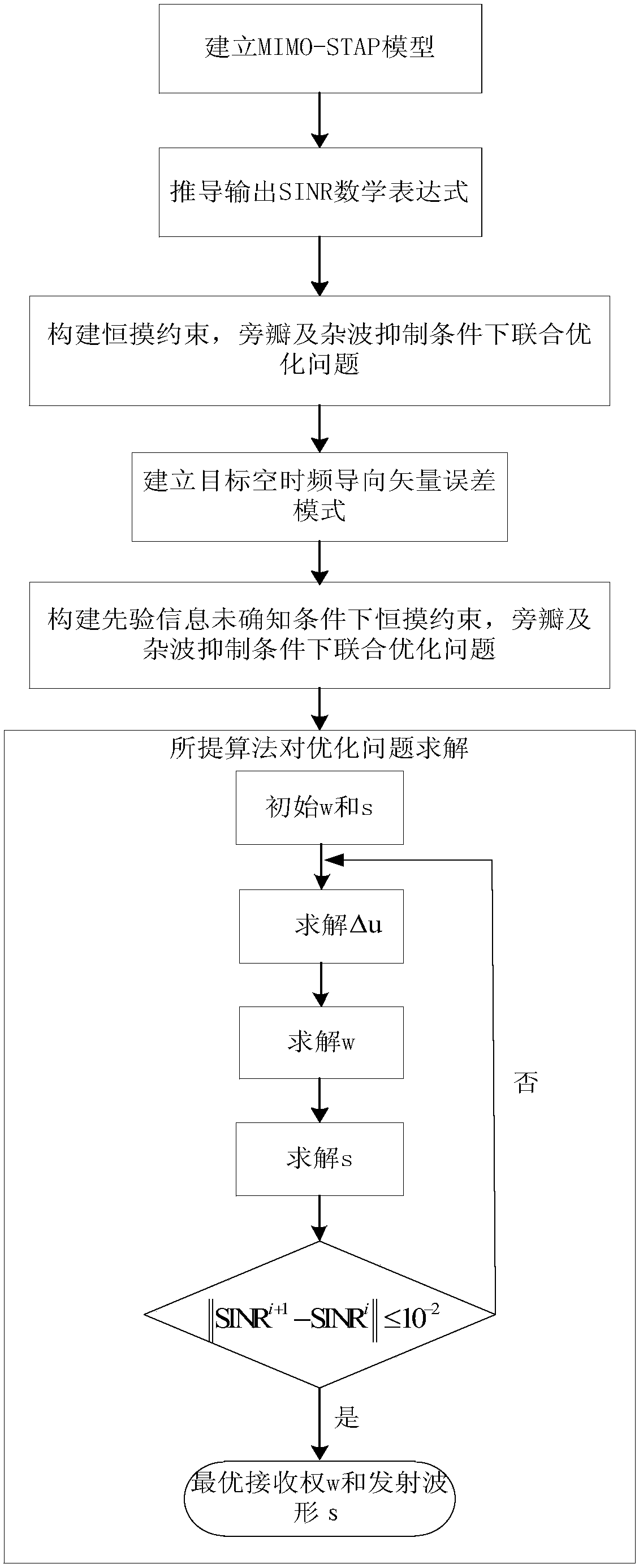
[0117] Such as figure 1 Shown is the flow chart that the present invention realizes.

[0118] Include the following steps:

[0119] Step 1: Establish MIMO-STAP detection model

[0120] The transceiver arrays are all uniform linear arrays, the numbers of receiving array elements and transmitting array elements are N and M respectively, and the spacing between transmitting and receiving arrays is d R and d T , and are distributed in parallel. The radar platform flies in a straight line at a constant speed along the direction of the transceiver array, and the pulse interval is T.

[0121] In this scenario, the present invention will first model the target, clutter and noise respectively:

[0122] Record the transmitted signal matrix as S=[s 1 ,s 2 ,...s M ] T , where s m ∈C K×1 Indicates the waveform sampling of the mth transmitting unit...


PUM


Abstract

Aiming at a problem that multi-input multiple-output (MIMO) radar space-time adaptive processing (STAP) detection performance is sensitive to a parameter estimation error so that system detection probability robustness is poor, the invention provides a transmitted-waveform and receiving-weight joint robust optimization method under the condition that target prior information is unascertained. According to a maximum output signal to interference and noise ratio (SINR) criterion, under the constraints of a transmitted waveform constant module characteristic, a sidelobe, clutter suppression and the like, based on a parameter estimation error convex set, a transmitted-waveform and receiving-weight joint robust optimization problem is constructed. In order to solve an acquired complex non-linear problem, an iteration algorithm is provided. In the algorithm, each step can be converted into a semi-definite programming problem (SDP) so that a high-efficient solution can be acquired. Value simulation shows that the algorithm can be used to significantly improve the detection robustness of a MIMO-STAP radar compared with a non-robust algorithm and a uncorrelated waveform.

Description

technical field [0001] The invention belongs to the field of radar signal processing, and in particular relates to a joint robust optimization method for transmitting and receiving that improves the worst detection performance of MIMO-STAP when the prior information of the target is not known. Background technique [0002] In recent years, with the vigorous development of multiple-input multiple-output (MIMO) communication, and the demand for new theories and technologies for radar to break through its own limitations, the concept of MIMO radar emerged as the times require. In contrast to conventional phased array radars, which can only transmit coherent waveforms, MIMO radars can utilize multiple transmit elements to transmit nearly arbitrary waveforms. According to the distance between adjacent array elements, MIMO radar can be divided into distributed MIMO radar and centralized MIMO radar. Distributed MIMO radar has a large distance between adjacent array elements, and c...

Claims


Application Information

Patent Timeline
IPC IPC(8): G01S7/02
CPCG01S7/02
Inventor 王洪雁乔惠娇周梦星
Owner DALIAN UNIV
Why Eureka
Try Eureka