Container type data center system based on U position non-occupied management system

A management system and data center technology, applied in the direction of data center, data processing center, support structure installation, etc., can solve the problems of complex installation and operation and maintenance, equipment occupying U space, etc., to achieve the convenience of assistance, convenient maintenance, and solution Difficult to install and maintain

Pending Publication Date: 2018-08-31
ZHENGZHOU YUNHAI INFORMATION TECH CO LTD
0 Cites 0 Cited by

AI-Extracted Technical Summary

Problems solved by technology

[0005] The purpose of the present invention is to provide a container-type data center system based on a management system that does not occupy a U-space, aiming to solve ...

Method used

Described management system equipment adopts advanced dual-core CORTEX A8 processor, carries ANDRIOD 4.04 operating system; Possess 1 RS232/RS485, 4 RS485 mouths, 8 DIs, 2 DOs output, 2 USBs, The front camera supports 3G/4G transmission, supports Wifi communication, and has a 10.1-inch industrial capacitive screen, supports configuration pages, and intuitively displays information in the computer room. The operation is simple and intuitive, and it is convenient for maintenance personnel to inspect and locate faults.
[0024] The partition wall in Figure 1 divides the container into two parts. The air-conditioning outdoor unit system includes two outdoor units. The outdoor unit is located in the partition space on the left side. The pipe passes through the hole, and then the hole is sealed with a sealing material to ensure the isolation effect of the container. In the isolated area on the right side of the container, the heat in the hot aisle is transferred to the outdoor unit through the refrigerant in the air conditioner in the end row. The liquid refrigerant absorbs the heat in the hot air passage and turns into a gaseous refrigerant that circulates to the outdoor unit. The gaseous refrigerant circulates to the surrounding air. Heat release, so that the gaseous refrigerant is converted into liquid refrigerant. In addition, due to the isolation technology of cold and hot aisles, the hot air from the hot aisle is evaporatively cooled by the inter-row air conditioner, and the cooled air is transported to the cold aisle on the side of the cabinet in the equipment container, and the cold air in the cold aisle flows After passing through the user equipment in the cabinet, it reaches the hot aisle on the other side of the cabinet. During this process, the cold air cools down the user equipment through heat exchange; the cold air itself becomes hot air after heat exchange, and then the hot air in the hot aisle is discharged The fan assembly of the air conditioner is sucked back into the unit for circulating cooling. Through this process, the cooling of the container heat dissipation equipment is realized, and the environme...

Abstract

The invention provides a container type data center system based on a U position non-occupied management system. The container type data center system comprises a container, a power distribution system, an AB door system, a management system and an air conditioning system, wherein the container is internally provided with a partition wall, the partition wall divides the container into two parts, one part is a data center system body, and the other part is an air conditioning outer machine system; the data center system body comprises an in-row air conditioner, a machine cabinet, a battery cabinet, a power distribution cabinet, an AB door and a management system; the in-row air conditioner adopts a refrigerant system and is connected with the air conditioning outer machine system through arefrigerant liquid pipe. The container type data center system based on the U position non-occupied management system has the advantages that it is achieved that container type data center managementsystem equipment does not occupy U positions any more, the problems that that the number of U positions which a user can use is decreased and the investment cost of a single cabinet of a user is increased, which are caused by the fact that management system equipment of a traditional container type data center occupies the U positions are solved, and the problem is solved that the installation andmaintenance of the traditional container type data center management system equipment have large difficulty.

Application Domain

ServersSpecial building +3

Technology Topic

Distribution power systemElectric power distribution +6

Image

  • Container type data center system based on U position non-occupied management system
  • Container type data center system based on U position non-occupied management system
  • Container type data center system based on U position non-occupied management system

Examples

  • Experimental program(1)

Example Embodiment

[0019] In order to clearly illustrate the technical characteristics of the present invention, the present invention will be described in detail below through specific implementations and in conjunction with the accompanying drawings. The following disclosure provides many different embodiments or examples for implementing different structures of the present invention. To simplify the disclosure of the present invention, the components and settings of specific examples are described below. In addition, the present invention may repeat reference numbers and/or letters in different examples. This repetition is for the purpose of simplification and clarity, and does not indicate the relationship between the various embodiments and/or settings discussed. It should be noted that the components illustrated in the drawings are not necessarily drawn to scale. The present invention omits descriptions of well-known components and processing techniques and processes to avoid unnecessarily limiting the present invention.
[0020] The following describes in detail a container-type data center system based on a U-seat management system provided by an embodiment of the present invention with reference to the accompanying drawings.
[0021] Such as figure 1 As shown, the embodiment of the present invention discloses a containerized data center system based on a management system that does not occupy U positions, including: a container, a power distribution system, an AB door system, a management system, and an air-conditioning system. The wall divides the container into two parts, one part is the data center system, and the other part is the air conditioner outside machine system; wherein, the data center system includes: inter-row air conditioners, cabinets and battery cabinets, power distribution cabinets, AB doors and management systems; The room air conditioner adopts a refrigerant system, which is connected to the external air conditioner system through a refrigerant pipe.
[0022] In view of the container's anti-wind and rain-proof functions, the weather-tight door of the container-type data center system adopts a concave installation method. The 40-foot and 20-foot container data centers install weathertight doors in the container for internal testing. The door frame is sealed with special sealing materials. When in a wind and rain environment, because the sealed door is at a certain distance from the outside of the container, rainwater cannot easily enter the container. , It can have a certain wind and rain protection function to protect the normal operation of the equipment; in addition, because the sealed door is recessed, the door handle is also in the recessed space. When the container is transported, it also reduces the damage caused by the protruding door handle of the traditional container. Risks are also conducive to transportation safety.
[0023] The 40-foot and 20-foot container data centers are equipped with flange channel connection ports at the right end of the container. When cables are arranged, they can enter the container from the reserved pipeline channel. The dedicated pipeline channel is anti-corrosive and waterproof Function to reduce the risk of cable damage.
[0024] figure 1 The partition wall divides the container into two parts. The air conditioner outdoor unit system includes two outdoor units. The outdoor unit is located in the partition space on the left. The pipe passes through the hole, and then the hole is sealed with a sealing material to ensure the isolation effect of the container. In the isolated area on the right side of the container, the heat in the hot aisle is transferred to the outdoor unit through the refrigerant in the air conditioner between the end rows. The liquid refrigerant absorbs the heat in the hot air duct and turns into a gaseous refrigerant to circulate to the outdoor unit, and the gaseous refrigerant flows to the surrounding air. The heat is released, and the gaseous refrigerant is transformed into a liquid refrigerant. In addition, due to the use of the isolation technology of the hot and cold aisles, the hot air in the hot aisle will be evaporatively cooled by the inter-row air conditioning, and the cooled air will be transported to the cold aisle located on the side of the cabinet in the equipment container. The cold air flow in the cold aisle After passing the user equipment in the cabinet, it reaches the hot aisle on the other side of the cabinet. In this process, the cold air cools the user equipment through heat exchange; the cold air itself becomes hot air after the heat exchange, and then the hot air in the hot aisle is interspaced The fan components of the air conditioner are sucked back into the unit for cyclic cooling. Through this process, the cooling of the container heat dissipation equipment is realized, so that the environmental parameters are within the set range, and the environment in the data center is stable and reliable.
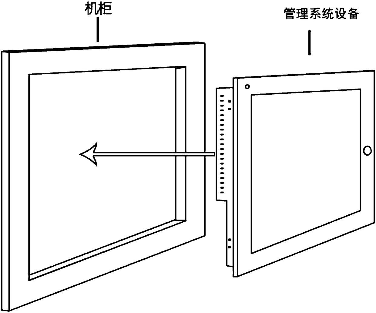
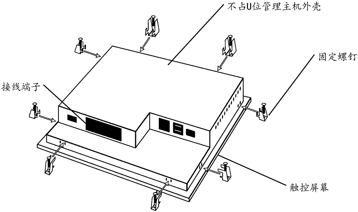
[0025] Such as Figure 2-3 As shown, the management system is composed of management system equipment, and the front door of the cabinet can be installed with management system equipment. The traditional data center monitoring system usually installs the management system equipment on the U positions in the ordinary cabinets, which causes a waste of space and poor maintainability and aesthetics.
[0026] The management system equipment is composed of a management host shell that does not occupy a U position, wiring terminals, a touch screen, fixing screws, and the like. Compared with the traditional monitoring system, the management system equipment has a simple structure and low manufacturing cost. The biggest difference is that the management system equipment is installed in a special management system equipment frame and installed on the front of the cabinet door, which is simple to install and fix, which is convenient for maintenance; When the management system equipment needs to be maintained, just loosen the up, down, left, and right screws to maintain the management system equipment, which is simple and convenient.
[0027] The management system equipment adopts advanced dual-core CORTEX A8 processor, comes with ANDRIOD 4.04 operating system; has 1 RS232/RS485, 4 RS485 ports, 8 DI, 2 DO output, 2 USB, front camera , Support 3G/4G transmission, support Wifi communication, and with 10.1-inch industrial capacitance screen, support configuration page, intuitive display of computer room information, simple and intuitive operation, convenient for maintenance personnel to inspect and locate faults.
[0028] The containerized data center system has multiple intelligent data interfaces, which can be connected to UPS, power distribution cabinets, precision air conditioners, access control systems, temperature and humidity sensors, smoke detectors, temperature detectors, water leak sensors and network cameras.
[0029] The monitoring equipment can be installed in the front frame of the cabinet in layers, and the cabinet door can be connected and fastened by fixing screws to limit the rear end of the monitoring equipment; when the equipment needs maintenance, the fixing screws can be loosened to make the monitoring The equipment is directly launched for easy maintenance.
[0030] The embodiment of the present invention realizes that the management system of the containerized data center no longer occupies the U positions, and solves the problem that the traditional containerized data center management system equipment occupies the U positions. The problem of poor economic benefits of containerized data centers and increased investment cost of U-bit cabinets per customer unit. The management system equipment is installed in the front frame of the cabinet, which is simple to install and fix and convenient to maintain, and solves the problem of the difficulty of installation and maintenance of traditional containerized data center management system equipment. Simplifies the structural design and helps users to maximize the convenience of using the U position. The container data center is equipped with an inter-row air conditioner between the cabinet and the cabinet, and two battery cabinets and one at the end of the container equipment area In the first cabinet, the heights of all cabinets, power distribution cabinets, air conditioners, and battery cabinets are consistent. The equipment in the data center is monitored and managed 7*24 hours, and the stable and reliable operation of the business system is guaranteed.
[0031] The above descriptions are only preferred embodiments of the present invention and are not intended to limit the present invention. Any modification, equivalent replacement and improvement made within the spirit and principle of the present invention shall be included in the protection of the present invention. Within range.

PUM

no PUM

Description & Claims & Application Information

We can also present the details of the Description, Claims and Application information to help users get a comprehensive understanding of the technical details of the patent, such as background art, summary of invention, brief description of drawings, description of embodiments, and other original content. On the other hand, users can also determine the specific scope of protection of the technology through the list of claims; as well as understand the changes in the life cycle of the technology with the presentation of the patent timeline. Login to view more.

Similar technology patents

Seismic bracing

PendingCN113685647AFlexible and adjustable angleEasy to install and fix
Owner:东荣(南京)建筑科技有限公司

Combined steering wheel protective shell

PendingCN114312964AEasy to install and fixImprove the feel of use
Owner:中山市澳凯汽车用品制造有限公司

Gasket structure passive wireless temperature sensor

Owner:SHANGHAI ZHIXIN INTELLIGENT ELECTRIC CO LTD +1

Classification and recommendation of technical efficacy words

  • easy maintenance
  • Easy to install and fix

Welding device and technique of axle housing assembly Y-shaped weld joint

ActiveCN101362248AHigh control reliabilityEasy maintenance
Owner:JIANGXI JIANGLING CHASSIS CO LTD

Bionic machinery chelonian with two-stage freedom degree flipper mechanism

InactiveCN101016081AIncreased angular velocity and rotational rangeeasy maintenance
Owner:PEKING UNIV

Clamping structure of circuit board

InactiveCN108012498AEasy take-out and feed-inEasy to install and fix
Owner:曹诗晴

Portable spherical infrared camera

InactiveCN104284072ASimplify camera structureEasy to install and fix
Owner:ZHONGSHAN ANLING STAR ELECTRONICS TECH

Automobile front suspension lower swing arm assembly

Owner:Ningbo Runzhou Automobile Fittings Co Ltd
Why Eureka
Try Eureka