Vapor compression-type refrigerator and method for controlling same

A compression refrigeration and compression technology, applied in refrigerators, compressors, compressors with reversible cycles, etc., can solve problems such as the performance decline of cooling and heating equipment with condensing performance, and achieve the effect of restraining energy consumption.

Active Publication Date: 2018-08-31
MITSUBISHI HEAVY IND THERMAL SYST
View PDF7 Cites 3 Cited by
  • Summary
  • Abstract
  • Description
  • Claims
  • Application Information

AI Technical Summary

Problems solved by technology

If the non-condensable gas stays in the condenser, the non-condensable gas acts as heat transfer resistance, hinders the condensation performance of the refrigerant in the condenser, and degrades the performance as a heating and cooling device.

Method used


Image

  • Vapor compression-type refrigerator and method for controlling same
  • Vapor compression-type refrigerator and method for controlling same
  • Vapor compression-type refrigerator and method for controlling same

Examples


Deformed example 1

[0088] In the present embodiment, the cooling water flow rate GWC is measured by the cooling water flow rate sensor 22, but even without the cooling water flow rate sensor 22, the cooling water flow rate GWC can be estimated as follows.

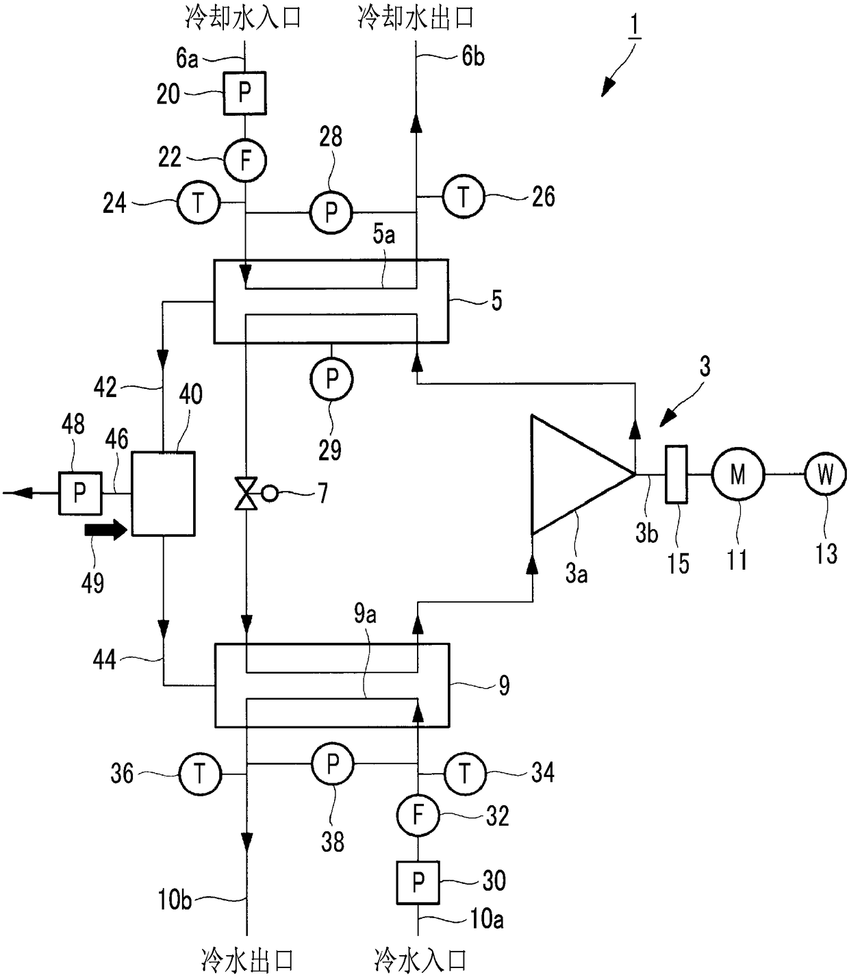
[0089] Using the cooling water flow rate sensor 32, the cooling water flow rate GWC is obtained from the heat balance of the entire turbo refrigerator 1 by the following equation.

[0090] GWC=(W+Qact) / ((TWCO-TWCI)×Cpcw×ρcw)…(3)

[0091] Here, W is the input electric power [kW] of the electric motor 11 measured by the power meter 13 . TWCO is the cooling water outlet temperature measured by the cooling water outlet temperature sensor 26 , and TWCI is the cooling water inlet temperature measured by the cooling water inlet temperature sensor 24 . Cpcw is the specific heat of cooling water [kWh / kg℃], ρ cw is the specific gravity of cooling water [kg / m 3 ].

[0092] Qact in the formula (3) is the actual measurement value [kW] of the cooling ca...


PUM


Abstract

The present invention provides a vapor compression-type refrigerator provided with an extraction device (40) including: a cooling unit for cooling gas that has been extracted from a condenser (5) andcondensing condensed gas; and an exhaust pump (48) for discharging, to the exterior, uncondensed gas that has been isolated without having been condensed by the cooling unit. A current temperature difference, which is the difference between the current saturation temperature in the condenser (5) and the current outlet temperature of a cooling water heat transfer tube (5a), and a planned temperature difference, which is a planned value, are computed. Using information on an in-tube fouling temperature difference elevation, which is a difference between the saturation temperature in the condenser (5) and the outlet temperature of the cooling water heat transfer tube (5a) and which is predetermined assuming in-tube fouling of the cooling water heat transfer tube (5a), the temperature difference elevation due to the current in-tube fouling is computed. The extraction device (40) is operated if the elevation of the current temperature difference from the planned temperature difference is greater by a predetermined value or more than the temperature difference elevation due to the current in-tube fouling.

Description

technical field [0001] The present invention relates to a vapor compression refrigerating machine equipped with an extraction device for extracting non-condensable gas from a condenser and a control method thereof. Background technique [0002] In cooling and heating equipment using refrigerant whose operating pressure is below atmospheric pressure during operation, noncondensable gases such as air intrude into the machine from the part below atmospheric pressure, pass through the compressor, etc., and stagnate in the condenser. If the non-condensable gas stays in the condenser, the non-condensable gas acts as a resistance to heat transfer, hinders the condensation performance of the refrigerant in the condenser, and degrades the performance of cooling and heating equipment. Therefore, the non-condensable gas is discharged from the condenser to the outside by using an extraction device to ensure normal performance. The extraction device introduces non-condensable gas into t...

Claims


Application Information

Patent Timeline
Patent Type & Authority Applications(China)
IPC IPC(8): F25B43/04
CPCF25B25/005F25B2500/19F25B2700/151F25B2700/195F25B2700/21161F25B2700/21171F25B43/043F25B49/02F25B2339/047F25B2600/021Y02B30/70F25B41/34F25B13/00F25B39/04
Inventor 和岛一喜栂野良枝三吉直也
Owner MITSUBISHI HEAVY IND THERMAL SYST
Why Eureka
Try Eureka