A device that generates an ion beam

A technology of ion beams and ion sources, applied in the field of ion sources, can solve problems such as the operation of ion sources or the adverse effects of life

Active Publication Date: 2021-03-02
VARIAN SEMICON EQUIP ASSOC INC
View PDF6 Cites 0 Cited by
  • Summary
  • Abstract
  • Description
  • Claims
  • Application Information

AI Technical Summary

Problems solved by technology

Additionally, these temperatures can adversely affect ion source operation or lifetime

Method used


Image

  • A device that generates an ion beam
  • A device that generates an ion beam
  • A device that generates an ion beam

Examples


Embodiment Construction

[0019] Embodiments are described herein in conjunction with an indirectly heated cathode (IHC) ion source. However, other ion sources such as Bernas and Freeman ion sources or RF ion sources may be used. Therefore, the present invention is not limited to the specific examples set forth below.

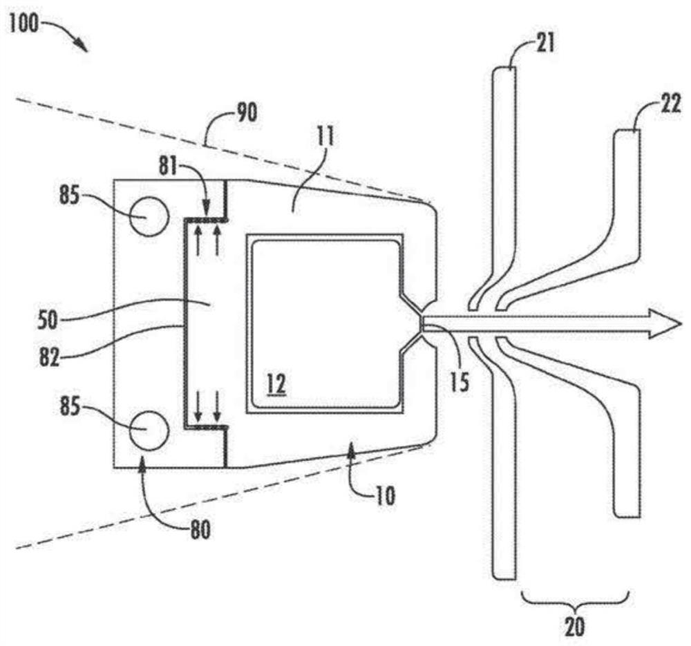
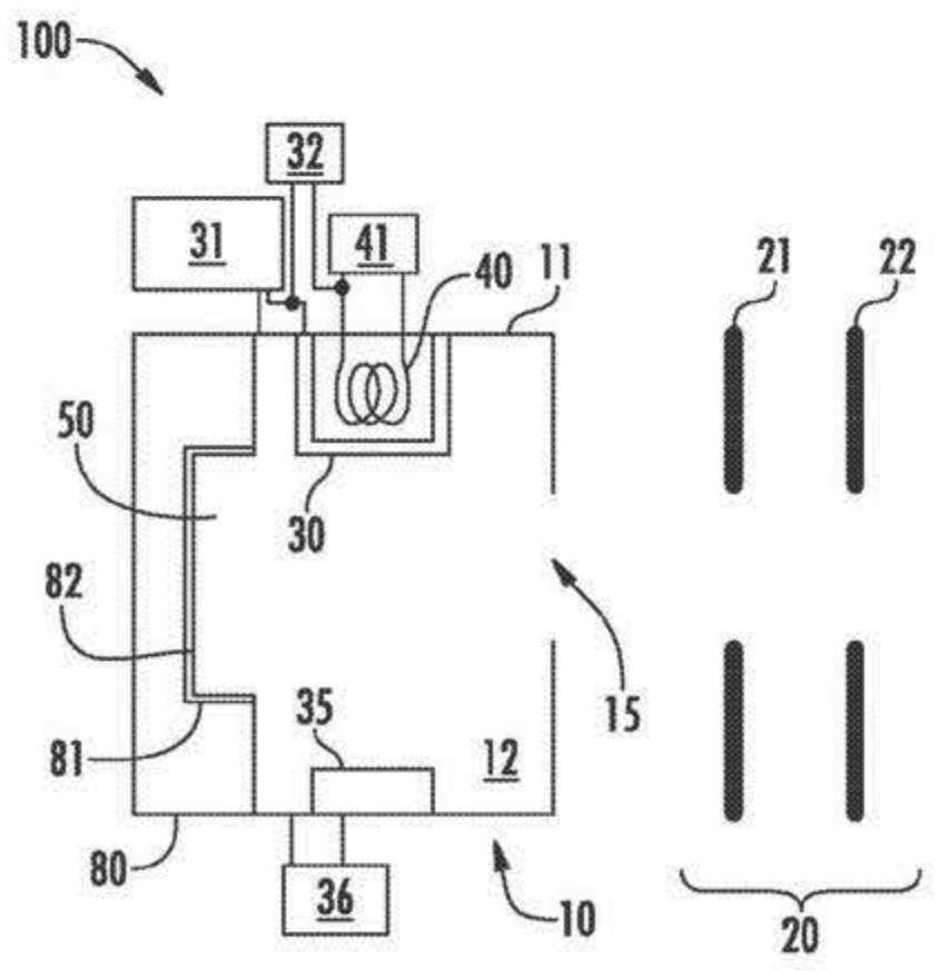
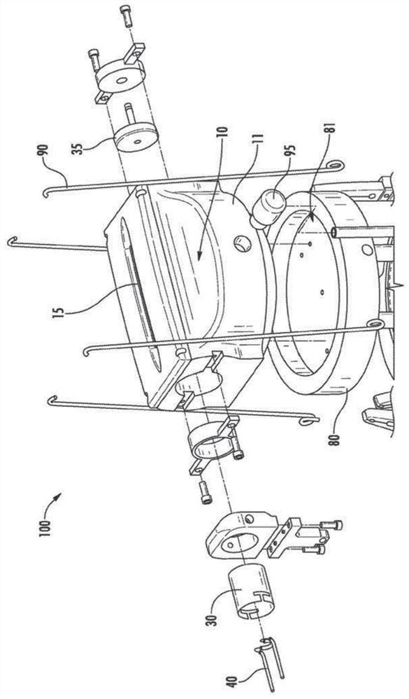
[0020] figure 1 A representative setup that can be used to generate an ion beam is shown. The apparatus 100 includes an ion source 10 and a heat sink 80 . Ion source 10 may be an indirectly heated cathode (IHC) ion source, although other ion sources may also be used. Ion source 10 has a plurality of chamber walls 11 that define an ion source chamber 12 . The chamber wall 11 may be constructed from an electrically conductive material. One of the chamber walls 11 has an extraction aperture 15 through which ions can be extracted from the ion source chamber 12 . Outside the ion source chamber 12 and near the extraction aperture 15 there are one or more electrodes 20 . In certain embo...


PUM


Abstract

The invention discloses a device for generating ion beams. A portion of the ion source with improved temperature control therein is located within a cavity in the heat sink, wherein a portion of the ion source and the cavity are each shaped such that expansion of the ion source results in high pressure thermal contact with the heat sink. For example, the ion source may have a tapered cylindrical end that fits within a cavity in the heat sink. Thermal expansion of the ion source causes the tapered cylinder end to press against the cavity of the heat sink. By properly selecting the temperature of the heat sink, the temperature and flow rate of the coolant fluid passing through the heat sink, and the size of the gap between the heat sink and the ion source, the temperature of the ion source can be controlled.

Description

technical field [0001] The present invention relates to an ion source, and more particularly to an ion source in which the temperature can be controlled and adjusted by a heat sink. Background technique [0002] Ion implantation is a standard technique for introducing conductivity-altering impurities into workpieces. The desired impurity material is ionized in the ion source, the ions are accelerated to form an ion beam having a prescribed energy, and the ion beam is directed toward the surface of the workpiece. The energetic ions in the beam penetrate most of the workpiece material and become embedded in the crystalline lattice of the workpiece material to form a region of desired conductivity. [0003] To generate an ion beam, an ion source typically consumes a large amount of power. While the vast majority of this power is used to convert molecules into the desired ionic species, a portion of this power is converted into heat. In some embodiments, the heat can increase...

Claims


Application Information

Patent Timeline
Patent Type & Authority Patents(China)
IPC IPC(8): H01J37/317H01J37/08
CPCH01J37/08H01J37/3171H01J2237/002H01J37/3002
Inventor 史考特·C·后登具本雄布兰特·S·宾斯理查尔·M·怀特肯尼士·L·斯塔克斯艾利克·R·科步
Owner VARIAN SEMICON EQUIP ASSOC INC
Why Eureka
Try Eureka