Variable-rigidity flexible grabbing device

A grasping device and variable stiffness technology, applied in the directions of manipulators, program-controlled manipulators, chucks, etc., can solve the problems of high manufacturing cost of rigid grippers, reduced success rate, unstable lateral buckling, etc., and achieve continuous and rapid stiffness. , Continuously and rapidly changing, the effect of large variable stiffness range

Active Publication Date: 2018-09-04
NINGBO INST OF MATERIALS TECH & ENG CHINESE ACADEMY OF SCI +1
View PDF6 Cites 26 Cited by
  • Summary
  • Abstract
  • Description
  • Claims
  • Application Information

AI Technical Summary

Problems solved by technology

However, rigid grippers with complex and high-precision sensing elements are often expensive to manufacture, low in cost performance, and low in operating efficiency; although flexible gripper-type end effectors have the advantages of flexible mechanisms, they can also be realized through ingenious design. The function of variable stiffness, but the problem of lateral buckling instability caused by the parasitic motion in the process of clamping the object based on the configuration of the branch chain of the single flexible mechanism still exists, and it cannot guarantee the stability of the clamping operation. During the process, the object is always clamped in parallel. This phenomenon often reduces the success rate for some high-precision operation tasks. In addition, it also has problems with system stability and fluency; although the soft gripper-type end effector is manufactured It is simple and low in cost, but for precision assembly and fields that require a large grasping force, the dynamic stability, grasping accuracy, and maximum clamping force during the grasping process often cannot meet the requirements of these high-precision tasks; and Due to the complexity of the multi-fingered dexterous hand end effector, its cost is often high, and its rich degrees of freedom and flexibility are actually not needed for many gripping tasks

Method used


Image

  • Variable-rigidity flexible grabbing device
  • Variable-rigidity flexible grabbing device
  • Variable-rigidity flexible grabbing device

Examples


Embodiment Construction

[0028] The following is attached figure 1In 5, the preferred embodiments of the present invention will be further described in detail, so as to understand the purpose, features and advantages of the present invention more clearly. It should be understood that the embodiments shown in the drawings are not intended to limit the scope of the present invention, but only to illustrate the essence of the technical solutions of the present invention.

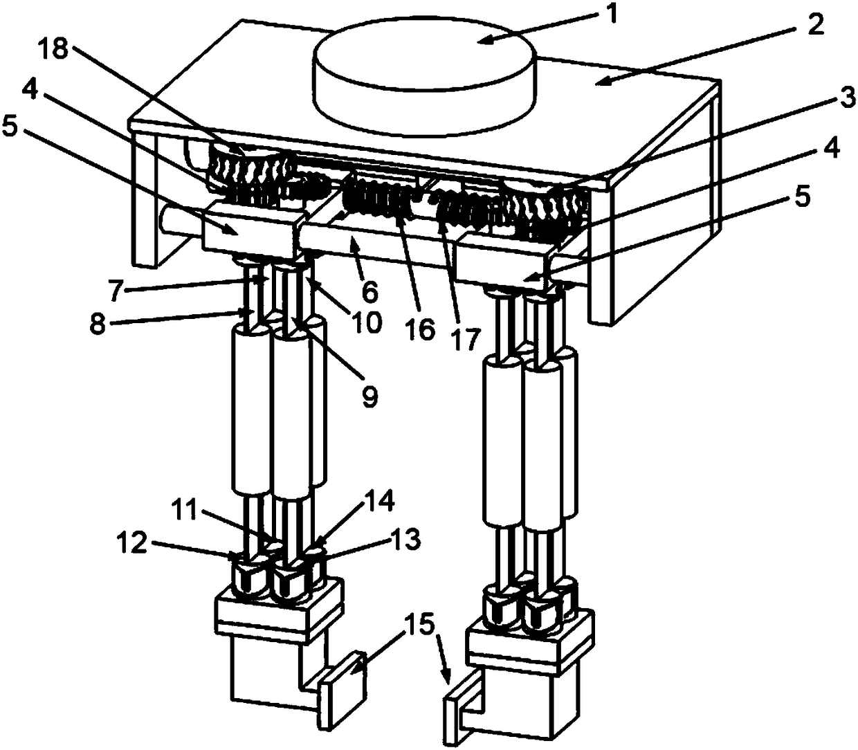
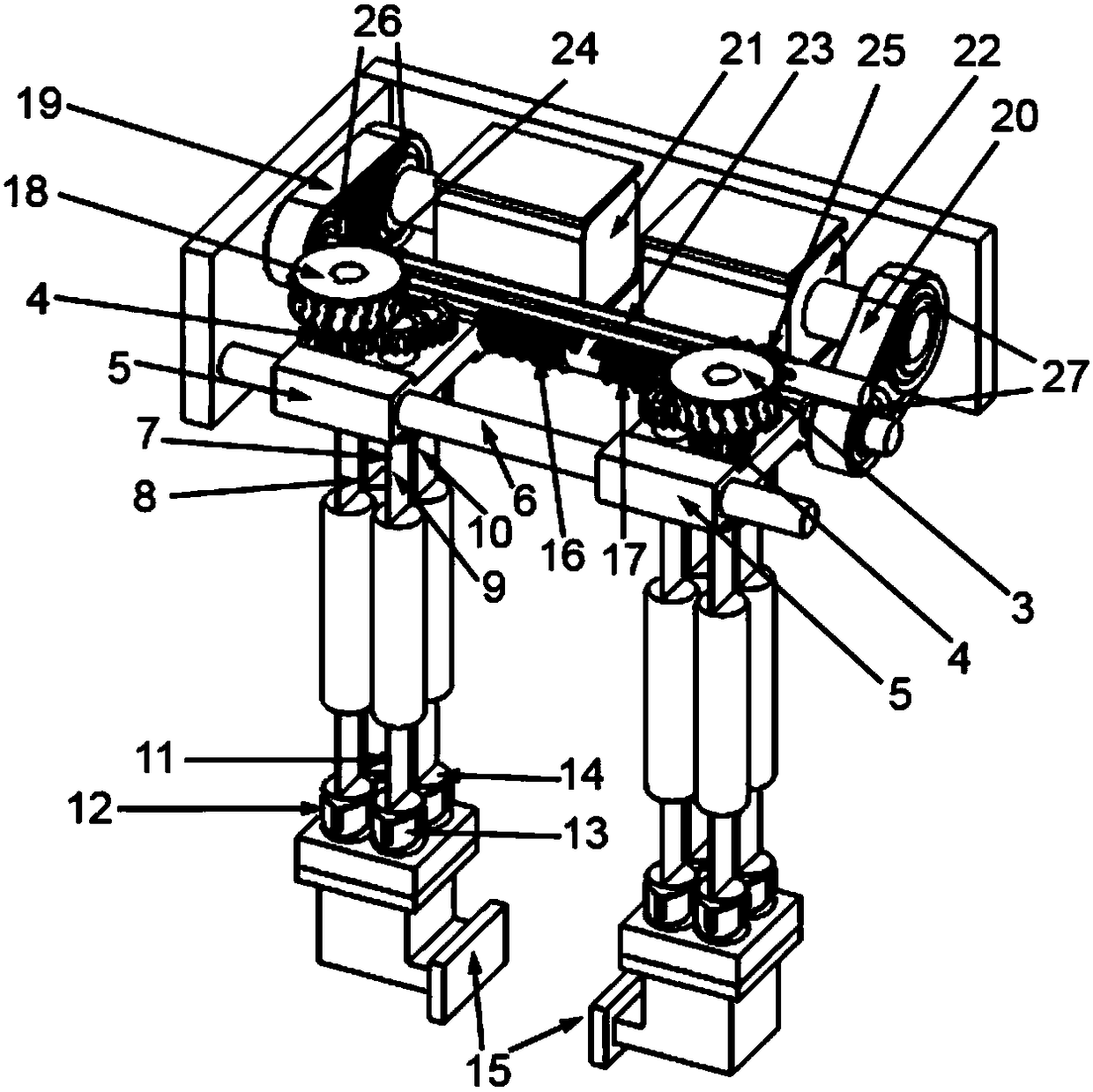
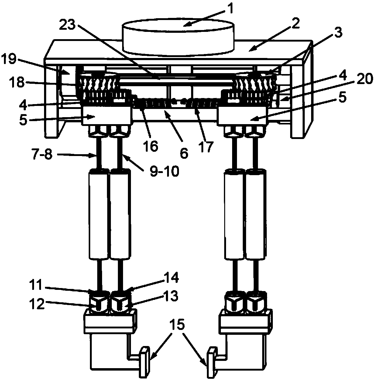
[0029] Figure 1 to Figure 5 It is a three-dimensional structural schematic diagram of the variable stiffness and compliant grabbing device in this embodiment, and the reference signs therein are: flange connection plate 1, casing 2, right-handed worm wheel 3, pinion 4, slider 5, linear guide rail 6, sheet Spring flexible joints 7, 8, 9, 10, flexible universal joints 11, 12, 13, 14, jaws 15, right-handed screw 16, left-handed screw 17, left-handed worm wheel 18, stiffness adjustment drive timing belt 19, opening Closing motion transm...


PUM


Abstract

The invention discloses a variable-rigidity flexible grabbing device. The variable-rigidity flexible grabbing device comprises two sliding blocks arranged on a linear guideway in a sliding mode, and the sliding blocks are driven by an opening and closing motion motor to do the movement so as to enable the sliding blocks to be close to each other and away from each other; and each sliding block isconnected with a clamping jaw for grabbing operation through a variable-rigidity flexible parallel mechanism, and the variable-rigidity flexible parallel mechanism is driven by a rigidity adjusting motor so as to adjust the rigidity of the variable-rigidity flexible parallel mechanism. In the working state, the parallel clamping displacement of the clamping jaws in the opening and closing movementdirection is controlled through driving of the opening and closing motion motor; and the clamping rigidity of the clamping jaws on the opening and closing movement is controlled through driving of the rigidity adjusting motor. According to the variable-rigidity flexible grabbing device, the clamping rigidity of the grabbing device in the opening and closing movement direction can be continuouslychanged so as to adapt to the clamping operation of objects with different shapes and different masses; and the grapping device can be used as a tail end effector of a robot and is particularly suitable for the fields of operational tasks, precision assembly and the like in the non-structural environment.

Description

technical field [0001] The invention relates to an end effector used in the field of robots, in particular to a flexible gripping device with variable stiffness. Background technique [0002] In recent years, more and more robots and humans have appeared in the factory workshop to work together, which is the so-called "human-machine collaboration" scenario; however, in this process, the relationship between humans, robots and the unstructured environment outside Inevitable collisions will inevitably occur between robots, so safety will become an important performance indicator for the next generation of robots. Since the end effector of the robot is the only interface for the robot to directly contact with people and external objects, it is very important to focus on the safety of the key component of the end effector of the robot. [0003] From the perspective of performing grasping and assembly tasks, robot end effectors are mainly divided into four categories: rigid grip...

Claims


Application Information

Patent Timeline
Patent Type & Authority Applications(China)
IPC IPC(8): B25J9/00B25J15/00
CPCB25J9/003B25J15/00
Inventor 杨桂林李建钢王慰军方灶军陈庆盈张驰
Owner NINGBO INST OF MATERIALS TECH & ENG CHINESE ACADEMY OF SCI
Why Eureka
Try Eureka