Circular track magnetic levitation vehicle energy storage system

A circular track and energy storage system technology, applied in propulsion systems, vehicle components, electric vehicles, etc., can solve the problems of large sensors and controllers, high power consumption and low reliability of electromagnetic levitation technology, and achieve flexible response power Adjustment, low cost, and efficiency-enhancing effects

Inactive Publication Date: 2018-09-04
INST OF ELECTRICAL ENG CHINESE ACAD OF SCI
View PDF8 Cites 10 Cited by
  • Summary
  • Abstract
  • Description
  • Claims
  • Application Information

AI Technical Summary

Problems solved by technology

However, electromagnetic levitation technology consumes a lot of power, and the sensors and controllers are bulky, expensive, complicated to control, and low in reliability; superconducting levitation requires refrigeration equipment, so it also has large volume, high energy consumption, complex structure, and high cost. and other shortcomings
When maglev technology is applied to maglev mechanical energy storage, the shortcomings of the above two maglev technologies become more obvious

Method used


Image

  • Circular track magnetic levitation vehicle energy storage system
  • Circular track magnetic levitation vehicle energy storage system
  • Circular track magnetic levitation vehicle energy storage system

Examples


Embodiment 1

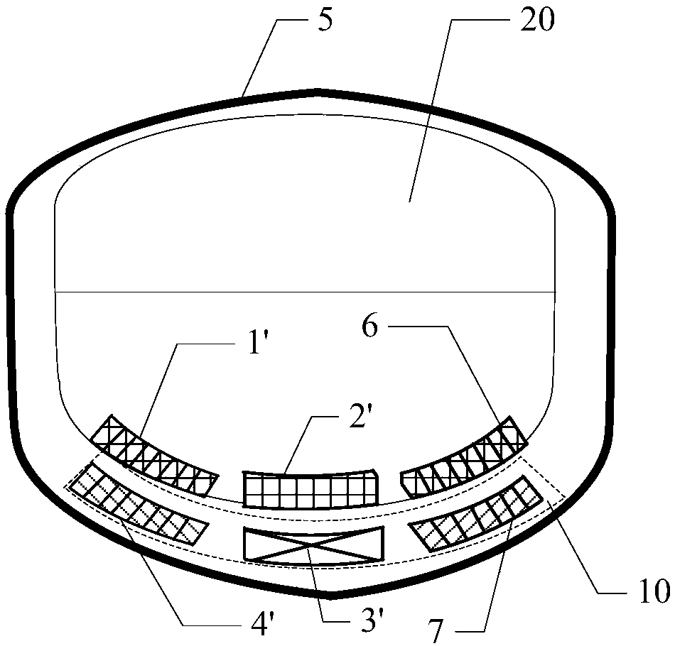
[0048] Such as figure 2 In the shown embodiment 1 of the present invention, viewed from a cross section, the vehicle 20 includes a first vehicle-mounted permanent magnet block 1' and a second vehicle-mounted permanent magnet block 6, and the first vehicle-mounted permanent magnet block 1' and the second vehicle-mounted permanent magnet block 1' The magnet blocks 6 are concentratedly arranged at the lower part of the vehicle; the track 10 may include the first track permanent magnet block 4' and the second track permanent magnet block 7, the first track permanent magnet block 4' and the second track permanent magnet block 7 is also correspondingly concentrated on the top of the track. The first vehicle-mounted permanent magnet block 1', the second vehicle-mounted permanent magnet block 6, the first track permanent magnet block 4' and the second track permanent magnet block 7 are all composed of a plurality of small permanent magnets, thereby ensuring the running stability of t...

Embodiment 2

[0050] Such as image 3 The shown embodiment 2 of the present invention, viewed from the cross section, the first track permanent magnet block 4', the second track permanent magnet block 7, the first controllable track 10 used to realize the suspension and guidance of the vehicle The heights of the excitation module 8 and the second controllable excitation module 9 are higher than the positions of the first vehicle-mounted permanent magnet block 1 ′ and the second vehicle-mounted permanent magnet block 6 in the vehicle 20 . The first controllable excitation module 8 and the second controllable excitation module 9 are hybrid magnets composed of electric excitation and permanent magnets, which can increase the running stability of the vehicle.

Embodiment 3

[0052] Such as Figure 4 In the shown embodiment 3 of the present invention, from the cross section, when the track is U-shaped, the first track permanent magnet block 4' and the second track permanent magnet block 7 in the track 10 can be used Permanent magnets with rounded rectangular sides are used instead. The first controllable excitation module 8 and the second controllable excitation module 9 are also hybrid magnets composed of electric excitation and permanent magnets, and the shape of the hybrid magnets becomes a long rectangle. At this time, the shape of the cavity formed by the track wall 5 also becomes a rounded rectangle.


PUM


Abstract

A circular track magnetic levitation vehicle energy storage system comprises a track (10), a vehicle (20), a current conversion device (30) and a track wall (5). Vehicle-mounted permanent magnet blocks (1) and a vehicle drive magnetic pole (2) are fixed to the vehicle (20); and a track drive coil (3) and track permanent magnet blocks (4) are fixed to the track (10). When the circular track magnetic levitation vehicle energy storage system needs to store energy, the current conversion device (30) absorbs energy from a power grid, a moor system composed of the vehicle drive magnetic pole (2) andthe track drive coil (3) drives the vehicle (20) to rotate at an accelerated speed, and the stored kinetic energy is increased; and when the circular track magnetic levitation vehicle energy storagesystem needs to release the energy, the motor system works in an electric generator state, and generated electric energy is fed back to the power grid through the current conversion device (30). Levitation and guidance of the vehicle (20) are achieved through the vehicle-mounted permanent magnet blocks (1) and the track permanent magnet blocks (4), and friction between the vehicle (20) and the track (10) is reduced.

Description

technical field [0001] The invention relates to an energy storage system for a circular track magnetic levitation vehicle. Background technique [0002] The magnetic levitation mechanical energy storage system is a kind of mechanical energy storage method. It is an energy storage device based on electromechanical energy conversion. It uses the kinetic energy of a high-speed moving vehicle to store energy. When the grid needs energy, the moving vehicle decelerates and releases the stored energy. With the large-scale development and utilization of new energy sources such as wind energy and solar energy, there is an urgent need for large-scale energy storage. However, existing energy storage methods, such as battery energy storage, usually have disadvantages such as low efficiency, high cost, unfriendly to the environment, and slow response. [0003] In addition, in the magnetic levitation train technology, in order to use the magnetic field force to levitate the moving train...

Claims


Application Information

Patent Timeline
Patent Type & Authority Applications(China)
IPC IPC(8): B60L13/06H02K41/03
CPCB60L13/06H02K41/031
Inventor 肖立业史黎明韦统振韩立博
Owner INST OF ELECTRICAL ENG CHINESE ACAD OF SCI
Why Eureka
Try Eureka