Gravity and flywheel combined comprehensive physical energy storage system and energy storage method

An energy storage system, flywheel energy storage technology, applied in the direction of AC network load balancing, reducing/preventing power oscillation, single-network parallel feeding arrangement, etc., can solve the problems of retired battery recycling and processing, and poor adjustment of gravity energy storage power , renewable energy power fluctuations and other issues, to achieve the effect of shortening the working time interval, improving the continuity and stability, improving the power quality and operation safety

Pending Publication Date: 2022-07-22
INST OF ELECTRICAL ENG CHINESE ACAD OF SCI +1
View PDF1 Cites 2 Cited by
  • Summary
  • Abstract
  • Description
  • Claims
  • Application Information

AI Technical Summary

Problems solved by technology

[0006] In addition, it is generally believed that the gravity energy storage system has the problems of slow power response and poor adjustability. Chinese invention patent CN202110636103.7 proposes a comprehensive energy storage system based on chemical batteries and gravity energy storage, relying on chemical batteries Good power regulation characteristics of energy storage to solve the problem of power fluctuation of renewable energy and poor power regulation of gravity energy storage
However, chemical batteries operate under frequent charging and discharging conditions, and their service life will be affected, and there are also problems in the recycling of decommissioned batteries

Method used


Image

  • Gravity and flywheel combined comprehensive physical energy storage system and energy storage method
  • Gravity and flywheel combined comprehensive physical energy storage system and energy storage method
  • Gravity and flywheel combined comprehensive physical energy storage system and energy storage method

Examples


Embodiment 1

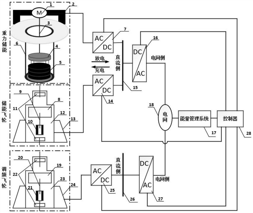
[0062] like figure 1 Shown is a schematic diagram of the working structure of the gravity energy storage module, flywheel energy storage module and frequency modulation flywheel module of the integrated physical energy storage system. The frequency modulation function of the integrated physical energy storage system is mainly realized by the frequency modulation flywheel module. During the frequency regulation process, the working states of the gravity energy storage module and the flywheel energy storage module remain basically unchanged. When the energy management system 17 monitors the power fluctuation of the power grid 18, it sends a dispatch signal to the controller 28, and the controller 28 sends a dispatch signal to the frequency modulation flywheel according to the dispatch signal. The module sends a control signal to control the FM flywheel machine-side converter 25 and the FM grid-side converter 27 in the FM flywheel module, and feedback controls the FM flywheel moto...

Embodiment 2

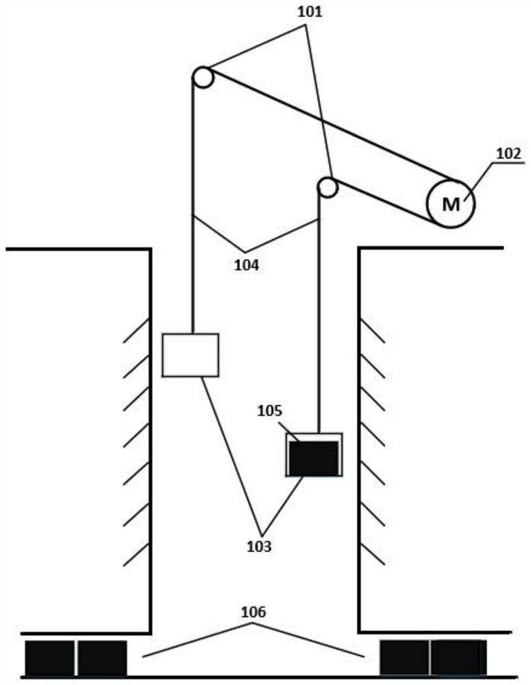
[0064] like figure 2 Shown is a schematic diagram of the traction drive structure of the double spreader or double cage of the gravity energy storage module, and the gravity energy storage module can adopt the double spreader or double cage traction drive mode and structure. The double spreader or double cage traction structure requires the shaft wall 103 to separate the two wells, and the gravity energy storage motor 102 connects the two spreaders or cages 103 in the The cage 103 carries weights 105 , and a plurality of the weights 105 are stored in the roadway 106 . When the load of one spreader or cage 103 is lowered, the other spreader or cage 103 is lifted without load, thereby eliminating the time interval caused by the lifting of a single gravity energy storage module without load.

Embodiment 3

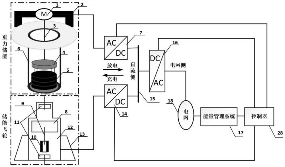
[0066] like image 3 Shown is a schematic diagram of the working structure of the energy storage module of the integrated physical energy storage system. The gravity energy storage module and the flywheel energy storage module in the integrated physical energy storage system are both composed of a single or multiple energy storage units. For the integrated module, in the structural diagram, the case where both energy storage modules use a single unit is exemplified.

[0067] like Figure 4 It is the output power characteristic diagram of the matched operation of two gravity energy storage units and a single flywheel energy storage unit.

[0068] In a separate gravity energy storage module, the gravity energy storage unit is modularly designed. The rated output power of a single gravity energy storage unit is 1MW, and the change of the output power of the unit with time presents a trapezoidal distribution, that is, it accelerates from zero to the highest speed within 1 minute...


PUM


Abstract

The invention provides a gravity and flywheel combined comprehensive physical energy storage system and an energy storage method. Wherein the gravity energy storage module comprises a gravity energy storage motor, an elevator, a steel cable, a lifting appliance, a weight block, a vertical shaft and the like; the flywheel energy storage module comprises an energy storage flywheel rotor, a flywheel main shaft, an energy storage flywheel motor, a bearing, a vacuum chamber, a protective shell and the like; the frequency modulation flywheel module has the same structure as the flywheel energy storage module; the comprehensive physical energy storage system further comprises a machine-side converter, a grid-side converter, a direct-current bus, an energy management system, a controller and the like. According to the invention, long-time stable discharge to the power grid is realized through cooperation of the gravity and the flywheel energy storage system, and the influence of frequent start and stop and intermittency of the gravity energy storage unit on the power grid and the system is avoided. While energy storage is realized, a special frequency modulation flywheel is equipped to complete the frequency modulation function of a power grid connected with the energy storage system, and the stability of the frequency of the power grid is also realized while the stability of the output power is ensured, so that the operation safety and reliability of the power grid are improved.

Description

technical field [0001] The invention belongs to the field of power grid energy storage such as gravity energy storage, flywheel energy storage and the like, and particularly relates to a comprehensive physical energy storage system and an energy storage method in which gravity is combined with a flywheel. Background technique [0002] The power generation and load demand in the power grid must maintain a real-time dynamic balance, but due to a series of external factors, the power load of residents will fluctuate greatly over time; the large-scale integration of renewable energy power will also It has a significant impact on the stable operation of the power grid. The introduction of power energy storage devices into the power grid can not only complete "peak shaving and valley filling", smooth load, realize the time and space transfer of electric energy, but also absorb large-scale renewable energy power, regulate frequency and voltage, and improve the stability and flexibi...

Claims


Application Information

Patent Timeline
Patent Type & Authority Applications(China)
IPC IPC(8): H02J3/28H02J3/30H02J3/24H02J3/46
CPCH02J3/28H02J3/30H02J3/241H02J3/466
Inventor 邱清泉赵永明肖立业聂子攀张京业滕玉平王粟罗晓悦周微微
Owner INST OF ELECTRICAL ENG CHINESE ACAD OF SCI
Why Eureka
Try Eureka