
Waste heat recovery type air treatment unit

An air handling unit and waste heat recovery technology, which is applied in the fields of construction and environmental protection, can solve the problems of ventilation, cross-contamination of exhaust air, low heat recovery efficiency, and large wind side flow resistance, and achieve small installation height requirements and high heat transfer efficiency , cost-saving effect

Pending Publication Date: 2018-09-04
GUANGZHOU INST OF ENERGY CONVERSION - CHINESE ACAD OF SCI
View PDF6 Cites 4 Cited by
  • Summary
  • Abstract
  • Description
  • Claims
  • Application Information

AI Technical Summary

Problems solved by technology

The heat recovery efficiency of the former is relatively high, but there is a risk of cross-contamination of fresh air and exhaust air; the latter mainly adopts a heat exchange method based on branch flow heat exchange. Although it can avoid the risk of cross-contamination of fresh air and exhaust air, Relatively low heat recovery efficiency
[0004] At present, the surface cooler of the air handling unit usually uses a finned tube evaporator, which has the disadvantages of large flow resistance on the wind side, poor heat transfer effect, large volume, easy ash formation, and high cost.

Method used


Image

  • Waste heat recovery type air treatment unit
  • Waste heat recovery type air treatment unit
  • Waste heat recovery type air treatment unit

Examples


Embodiment

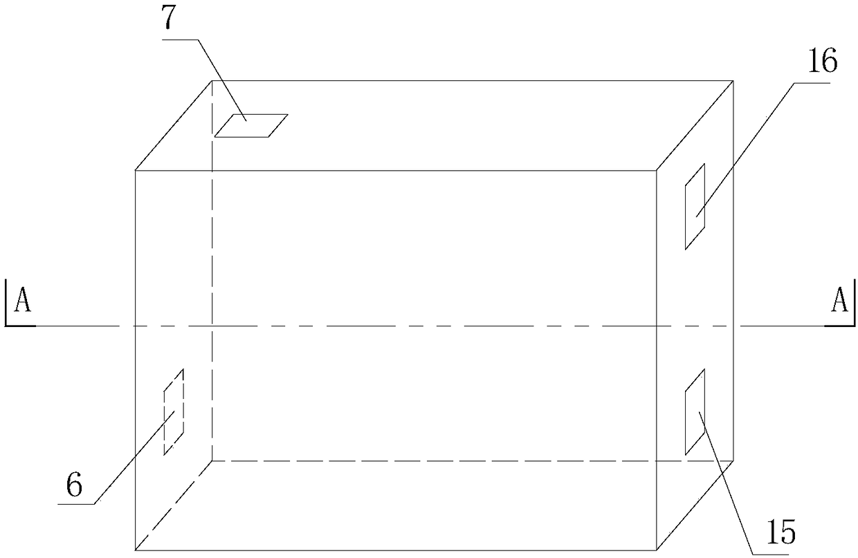
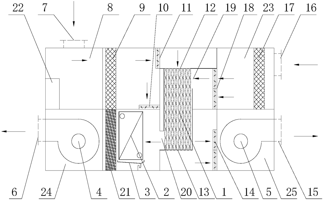
[0032] Such as figure 1 and figure 2 As shown, a waste heat recovery type air handling unit is a box structure, the upper left part of the box is the return air chamber 8, the upper right part is the fresh air chamber 23, the lower left part is the air supply chamber 24, and the lower right part is the exhaust chamber 25. The middle part is a three-dimensional variable structure high-efficiency heat recovery device 1.

[0033] The top surface of the air return chamber 8 is provided with a return air outlet 7, the bottom surface communicates with the air supply chamber 24 through the first air return valve 10, and the right side passes through the second air return valve 11, the return air inlet 12 and the three-dimensional variable structure for efficient heat recovery. The return air channel of the device 1 is connected, and a return air coarse filter 9 is arranged in the flow channel between the return air port 7 and the first return air valve 10 and the second return air ...


PUM


Abstract

The invention discloses a waste heat recovery type air treatment unit. The waste heat recovery type air treatment unit comprises a three-dimensional variable structure efficient heat recovery device,a three-dimensional variable structure efficient surface air cooler, a blower, an exhaust fan, a return air coarse filter and a fresh air coarse filter, wherein outdoor fresh air is treated by the fresh air coarse filter, then exchanges heat with indoor return air in the three-dimensional variable structure efficient heat recovery device and then is mixed with the indoor return air so as to exchange heat through the three-dimensional variable structure efficient surface air cooler and pressurize to be sent to a room by the blower; after the indoor return air passes through the return air coarse filter, a part of the indoor return air is mixed with the fresh air after heat exchange, and a part of the indoor return air exchanges heat with the outdoor fresh air in the three-dimensional variable structure efficient heat recovery device and then is discharged to the outside by the exhaust fan. The waste heat recovery type air treatment unit has the advantages of the compact structure and small size and is especially suitable for being installed in a building with limited space; the three-dimensional variable structure efficient heat recovery device is adopted, so that efficient heat recovery between fresh air and return air is realized; and the three-dimensional variable structure efficient surface air cooler is adopted, so that the heat exchange efficiency is improved, thereby achieving the purpose of energy conservation.

Description

technical field [0001] The invention relates to the technical fields of construction and environmental protection, in particular to a waste heat recovery type air handling unit. Background technique [0002] With the improvement of people's living standards, building energy consumption has also risen sharply. According to statistics, my country's building energy consumption accounts for about 20% of the country's total energy consumption. If the energy consumption of building construction is added, the construction and operation energy consumption of the entire building field accounts for as much as 36% of the total primary energy consumption of the whole society. Therefore, building energy efficiency is particularly important. Processing outdoor fresh air to meet indoor temperature and humidity requirements consumes a lot of energy, accounting for about 20-30% of air-conditioning energy consumption. Therefore, using building exhaust to pre-cool / preheat outdoor fresh air ca...

Claims


Application Information

Patent Timeline
Patent Type & Authority Applications(China)
IPC IPC(8): F24F7/08F24F11/39F24F11/58F24F11/64F24F11/77F24F11/84F24F12/00F24F13/24F24F13/28F24F13/30F28F21/08
CPCF24F7/08F24F11/39F24F11/58F24F11/64F24F11/77F24F11/84F24F12/002F24F12/006F24F13/24F24F13/28F24F13/30F28F21/084F24F2013/247Y02B30/56Y02B30/70
Inventor 尹应德朱冬生
Owner GUANGZHOU INST OF ENERGY CONVERSION - CHINESE ACAD OF SCI
Learn More