Non-contact electric energy transmission device and position detection method

A technology of power transmission and detection method, applied in circuit devices, battery circuit devices, transportation and packaging, etc., can solve problems such as limited applicability

Active Publication Date: 2018-09-04
NANJING UNIV OF AERONAUTICS & ASTRONAUTICS
View PDF2 Cites 6 Cited by
  • Summary
  • Abstract
  • Description
  • Claims
  • Application Information

AI Technical Summary

Problems solved by technology

Therefore, this method can only be used for secondary windings with a specific structure, spe

Method used


Image

  • Non-contact electric energy transmission device and position detection method
  • Non-contact electric energy transmission device and position detection method
  • Non-contact electric energy transmission device and position detection method

Examples


Embodiment 1

[0054] Figure 8-Figure 10 It is a schematic diagram of Embodiment 1 of the present invention.

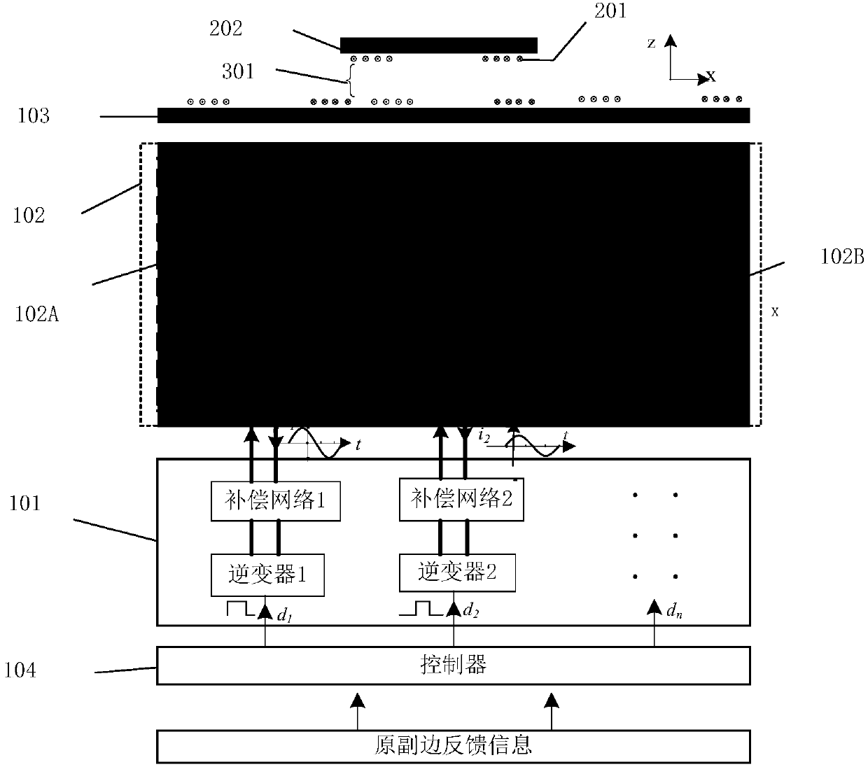
[0055] like Figure 8 As shown, the excitation winding of the device is located on the primary side, and consists of a pre-excitation power conversion unit 101, a pre-excitation winding unit 102A (coils 102A1, 102A2), a primary magnetic core 103, a controller 104, a secondary winding 201, and a secondary magnetic Core 202. There is an air gap 301 between the original side and the side side.

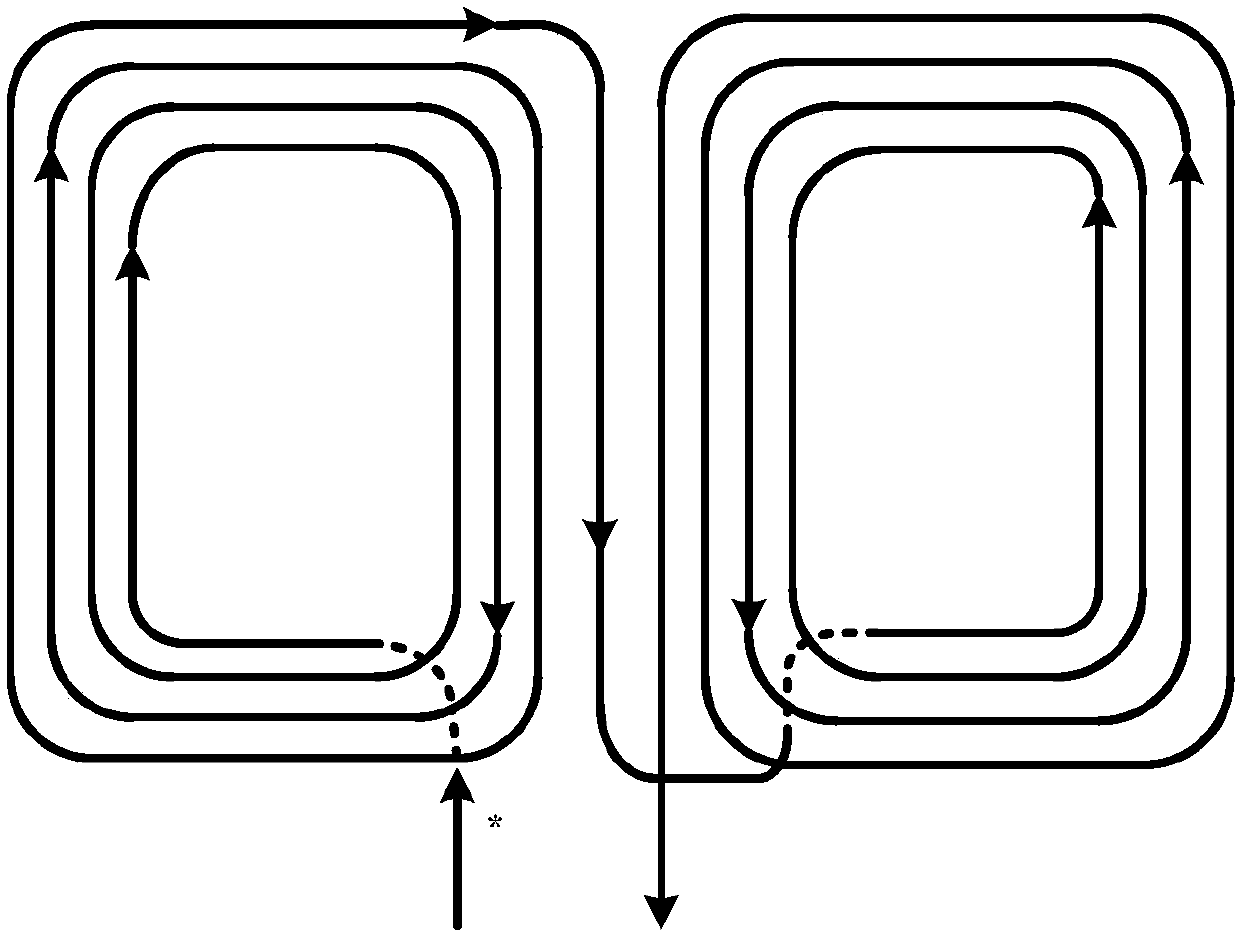
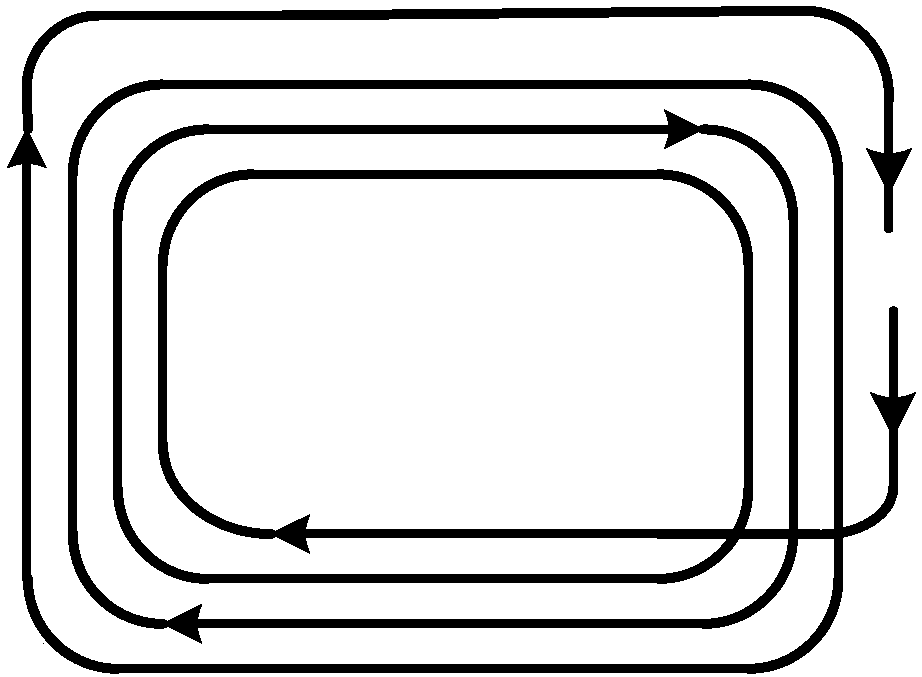
[0056] Figure 9 , Figure 10 It is a schematic diagram of the relative positions of the primary and secondary sides of the disk type and DD windings in this embodiment. As shown in the figure, the primary side pre-excitation coils 102A1 and 102A2 are linearly arranged along the x direction, overlapping each other by 50%. The width of the two coils in the x direction, that is, the transverse width is a. The magnitude and phase of the applied current can be freely and flexibly adjusted by...

Embodiment 2

[0074] Figure 11 , Figure 12 It is a schematic diagram of the winding of Embodiment 2 of the present invention.

[0075] The device used in this test case is Figure 8 Similarly, the power conversion unit 101 for pre-excitation, the primary-side pre-excitation winding unit 102A, the primary-side magnetic core 103 , the primary-side controller 104 , the secondary-side winding 201 , and the secondary-side magnetic core 202 . There is an air gap 301 between the original side and the side side.

[0076]Different from the first embodiment, the primary pre-excitation winding unit in this example is composed of three coils: 102A1, 102A2, and 102A2. The lateral width of each coil is a. The three coils on the primary side are arranged along a straight line (set as the x direction), and two adjacent coils overlap by 50%. The magnitude and phase of the applied current can be freely and flexibly adjusted by the controller, regardless of the load and coupling.

[0077] The specific...

Embodiment 3

[0087] Figure 13 A schematic diagram of the distribution of primary-side pre-excitation windings in this embodiment is given; 102A, 102B, 102C, 102D, 102E, and 102F are schematic diagrams of multiple primary-side pre-excitation winding units forming primary-side pre-excitation windings through translation and rotation. The rest of the non-contact power transmission device includes: a primary power conversion unit 101 (including an inverter and a compensation network), a primary magnetic core 103 , a primary controller 104 , a secondary winding 201 , and a secondary magnetic core 202 . There is an air gap 301 between the original side and the side side. The position detection method in this embodiment is similar to the above embodiment, and will not be repeated here.


PUM


Abstract

The present invention discloses a position detection method based on flexible traveling wave pre-excitation and a non-contact electric energy transmission device. The non-contact electric energy transmission device comprises a power conversion unit for pre-excitation, a pre-excitation winding, a primary side magnetic core, a primary side controller, a secondary side power winding, a secondary sidemagnetic core, a load and a secondary side power conversion unit. The position detection method comprises the steps that: free, flexible and variable excitation is applied to a primary side pre-excitation winding in advance to construct flexible traveling waves with adjustable magnetic field amplitudes, wave peaks and wave trough positions, a variable excitation extreme value is employed to search and find output feedback or excitation features corresponding to the peak of primary side sampling signals to determine and obtain the center position of the secondary side winding so as to provideposition information for alignment of the primary and secondary side winding or non-contact electric energy transmission system control. According to the position detection method based on flexible traveling wave pre-excitation, the primary side pre-excitation winding can be a primary side power emission winding, and can be additional winding. The method is suitable for two typical secondary sidewinding structures (a disc type and a DD type).

Description

technical field [0001] The invention relates to power electronics technology and non-contact power supply technology, in particular to a position detection method based on "flexible traveling wave pre-excitation" and a non-contact power transmission device. Background technique [0002] Non-contact power supply uses magnetic field coupling to realize "wireless power supply", that is, a non-contact transformer with completely separated primary and secondary sides is used to transmit electric energy through high-frequency magnetic field coupling, so that the primary side (power supply side) and secondary side (power consumption side) side) no physical connection. Compared with the traditional contact power supply, non-contact power supply is convenient and safe to use, without sparks and electric shock hazards, without dust accumulation and contact loss, without mechanical wear and corresponding maintenance problems, and can adapt to a variety of severe weather and environment...

Claims


Application Information

Patent Timeline
IPC IPC(8): H02J7/00H02J50/20H02J50/12H02J50/30H02J50/90
CPCH02J7/025H02J50/12H02J50/20H02J50/30H02J50/90
Inventor 陈乾宏高伟柯光洁耿玉川徐立刚张斌任小永张之梁
Owner NANJING UNIV OF AERONAUTICS & ASTRONAUTICS
Why Eureka
Try Eureka