Multi-degree-of-freedom spherical motor and speed reducing mechanism thereof

A technology of reduction mechanism and spherical motor, applied in the direction of magnetic circuit shape/style/structure, electric components, electrical components, etc., can solve the problem that the reducer cannot follow the three-degree-of-freedom drive of the spherical motor, and the motor is difficult to achieve three-degree-of-freedom full circle rotation , high manufacturing cost and extremely high installation accuracy requirements, etc., to achieve the effect of high integration, large range of motion, and low installation accuracy requirements

Pending Publication Date: 2018-09-04
HEBEI UNIV OF TECH
View PDF2 Cites 14 Cited by
  • Summary
  • Abstract
  • Description
  • Claims
  • Application Information

AI Technical Summary

Problems solved by technology

The document with the application number 201710152429.6 discloses a three-degree-of-freedom permanent-magnet spherical motor. The three-degree-of-freedom permanent-magnet spherical motor supported by universal balls uses 36 stator coils with independent power supply circuits to drive the motor rotor to rotate. However, due to the The motor adopts the way that the output shaft is connected with the flange, and it is difficult for the motor to realize three-degree-of-freedom full-circle rotation
The document with the application number 201521075361.9 discloses a gear transmission mechanism driven by a spherical motor. By setting a steering mechanism composed of a bevel gear at the rotor shaft end of the spherical motor, the deceleration and torque increase of the motor can be realized. However, the reduction mechanism uses a larg

Method used


Image

  • Multi-degree-of-freedom spherical motor and speed reducing mechanism thereof
  • Multi-degree-of-freedom spherical motor and speed reducing mechanism thereof
  • Multi-degree-of-freedom spherical motor and speed reducing mechanism thereof

Examples


Embodiment Construction

[0022] Specific examples of the present invention are given below. The specific embodiments are only used to further describe the present invention in detail, and do not limit the protection scope of the claims of the present application.

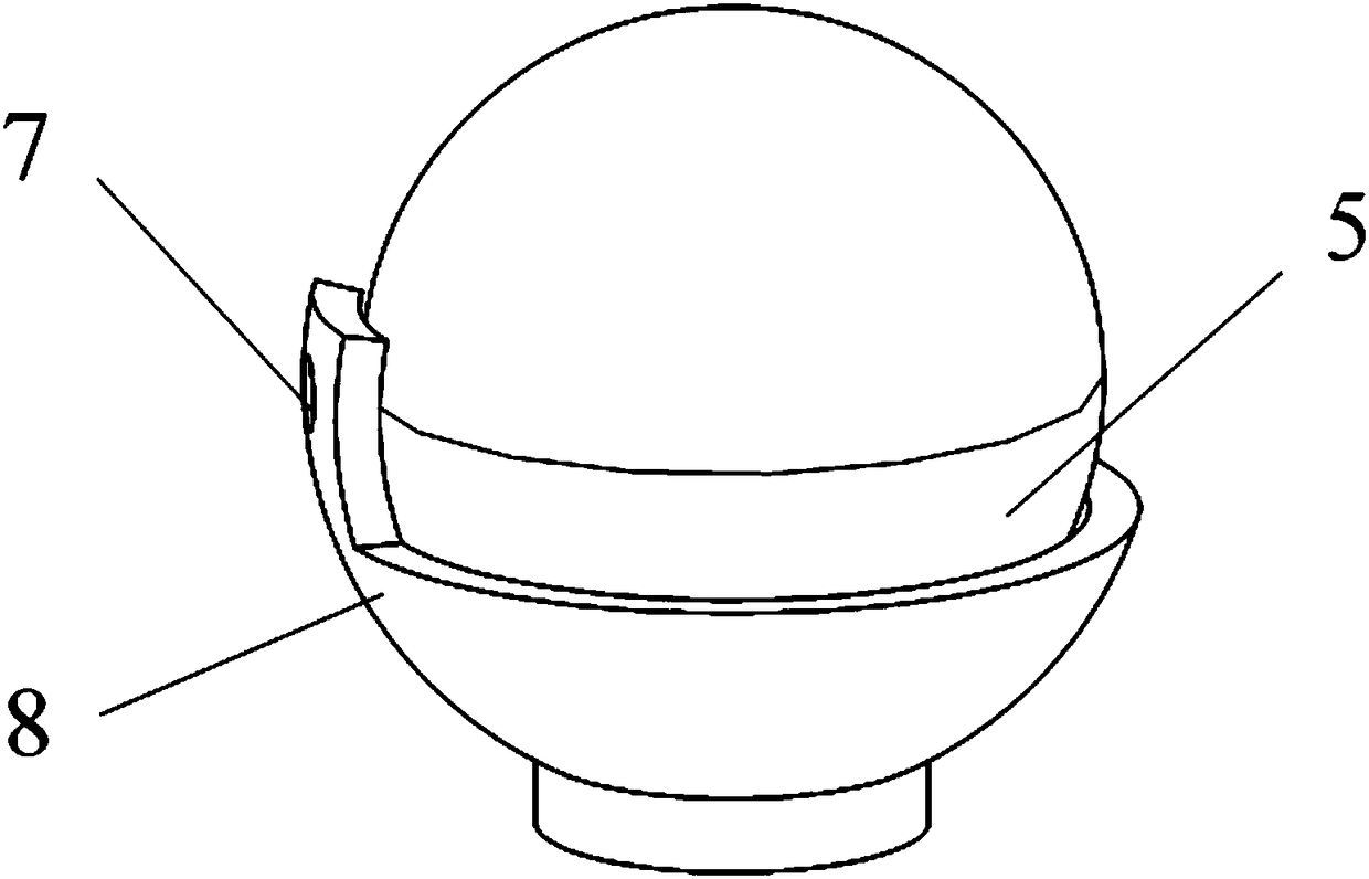
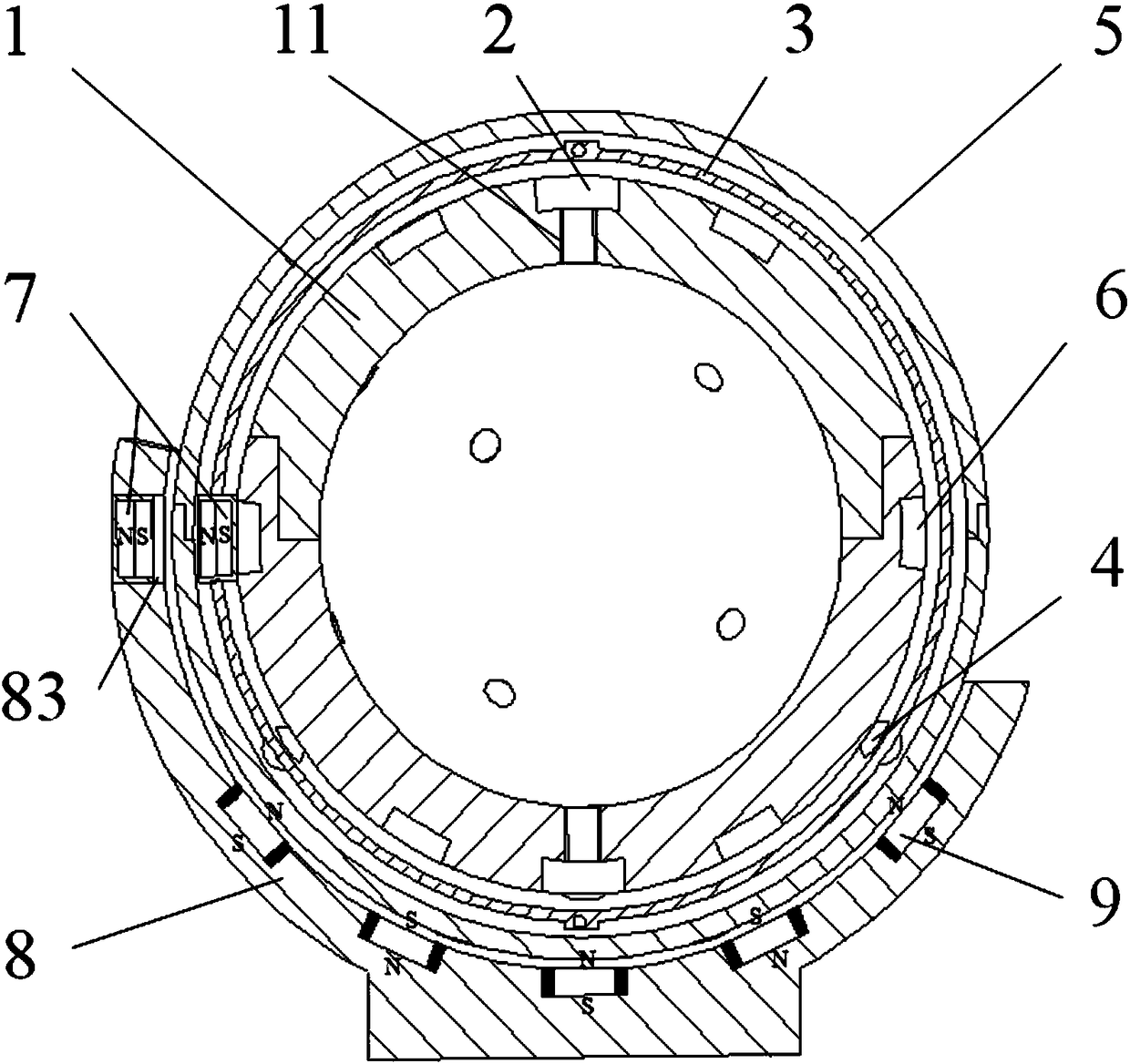
[0023] The invention provides a multi-degree-of-freedom spherical motor and its reduction mechanism (see Figure 1-7 , referred to as the device), it is characterized in that the device includes a motor rotor mechanism, a speed reduction mechanism and a motor stator mechanism;

[0024] The motor rotor mechanism includes a rotor 1 and a permanent magnet 2; the reduction mechanism includes a cage 3, balls 4, an output housing 5, a label 6 and a fixed magnet 7; the motor stator mechanism includes a stator support 8 and an electromagnet 9;

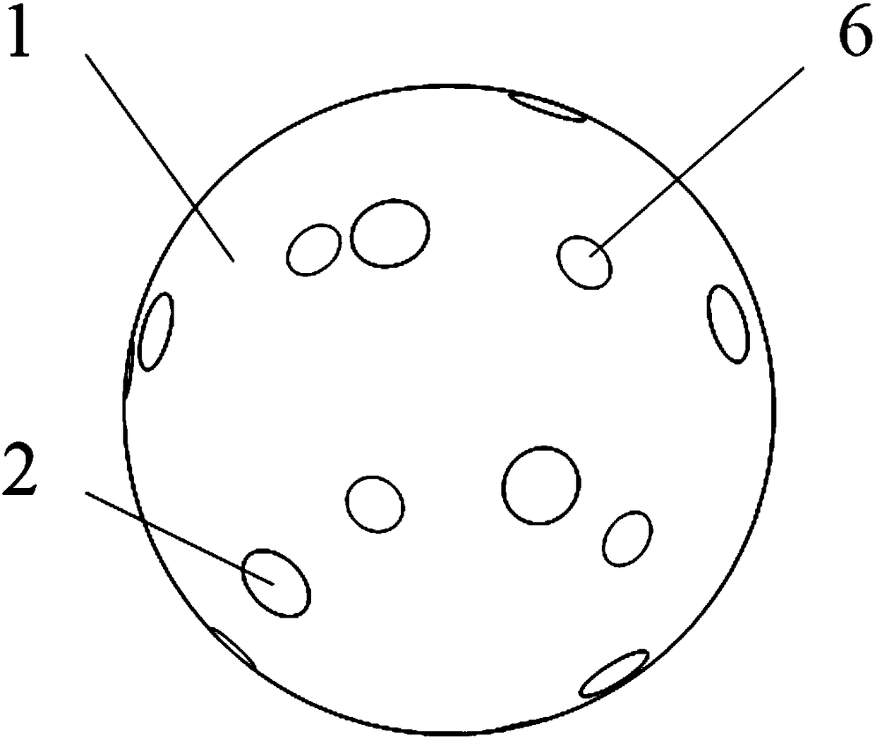
[0025] The rotor 1 is a hollow sphere structure, and several (14 in this embodiment) stepped holes 11 are evenly opened on the surface of the rotor 1, and there are threads in the stepped holes 11; severa...


PUM

PropertyMeasurementUnit
Thicknessaaaaaaaaaa
Thicknessaaaaaaaaaa
Thicknessaaaaaaaaaa

Abstract

The invention discloses a multi-degree-of-freedom spherical motor and a speed reducing mechanism thereof. The motor comprises a rotor, a permanent magnet, a holding rack, a ball, an output shell, a plurality of labels, a fixed magnet, a stator support and electromagnets, wherein the plurality of labels are uniformly embedded onto the surface of the rotor; the permanent magnet is connected to a step hole of the rotor; the holding rack is embedded onto the outer side of the rotor; the fixed magnet is placed in the fixed magnet seat of the holding rack; the output shell is embedded onto the outerside of the holding rack; the ball is placed in a ball through hole of the holding rack, and the outer surface is separately in contact with the outer surface of the rotor and the inner surface of the output shell; the electromagnet is fixed in the electromagnet seat of the stator support, the pole directions of adjacent two electromagnets are opposite, and the electromagnets are matched with thepermanent magnet; a plurality of positioning sensors are uniformly arranged on the inner surface of the stator support, and the positioning sensors are matched with the labels; and the fixed magnet is fixed in the magnet seat of the stator support, and is matched with the fixed magnet in the holding rack. The motor is simple and compact in structure, high in integrating degree and high in universality.

Description

technical field [0001] The invention relates to the field of motor design, in particular to a multi-degree-of-freedom spherical motor and a reduction mechanism thereof. Background technique [0002] With the rapid development of modern industrial technology, the application of robots has significantly improved productivity and reduced labor costs. However, when mechanical devices such as robots complete complex tasks, they often require multi-degree-of-freedom movements. For this reason, the combination of multiple traditional single-degree-of-freedom motors is generally used in engineering, and the multi-degree-of-freedom movement of the device is realized through the coordinated drive of multiple motors, so that the device is not only complex in structure and bulky, but also has low motion coordination and load Small capacity, limited movement space, slow response speed, poor dynamic performance and stability. The spherical motor can theoretically realize movement in any ...

Claims


Application Information

Patent Timeline
IPC IPC(8): H02K21/02H02K1/27H02K1/30H02K11/21
CPCH02K21/02H02K1/278H02K1/30H02K11/21
Inventor 李满宏马艳悦孙凌宇张小俊
Owner HEBEI UNIV OF TECH
Why Eureka
Try Eureka