

Mold cooling pipe wall limescale peeling device
A mold cooling and stripping device technology, which is applied in the direction of cleaning methods and utensils, cleaning hollow objects, chemical instruments and methods, etc., can solve the problems of low efficiency, incomplete cleaning, and high local temperature of molds, so as to improve cleaning quality and avoid cleaning Difficulty, effect of improving cleaning efficiency
- Summary
- Abstract
- Description
- Claims
- Application Information
AI Technical Summary
Problems solved by technology
Method used
Image

Examples
Embodiment Construction
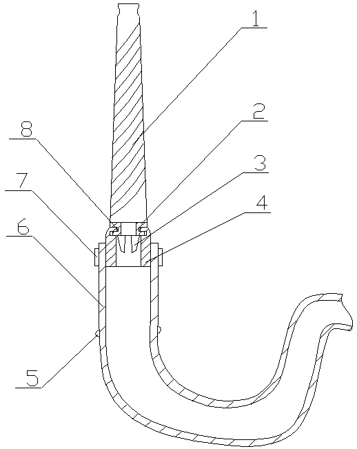
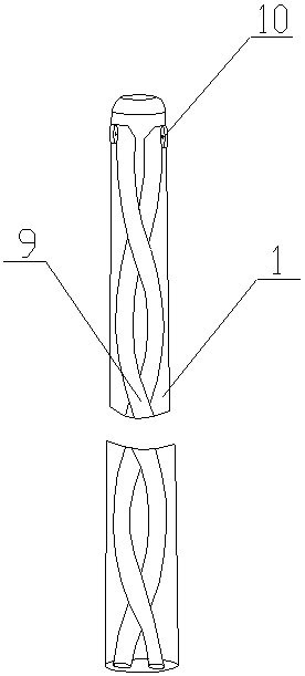
[0023] A mold cooling pipe wall scale stripping device of the present invention is realized in this way. When in use, the other end of the communication hose (6) is connected with the fluid medium, and the fluid medium is any one of high-pressure water, high-pressure air, and cleaning liquid. Mix one or more kinds, then extend the small end of the stripping tube (1) from the mouth of the mold cooling tube, and then open the fluid medium so that the fluid enters along the connecting hose (6) and impacts the ferrule (2) The rotating blade (3) at the bottom drives the rotating blade (3) to rotate, and then drives the ferrule (2) to rotate, and drives the stripping tube (1) to rotate through the ferrule (2). When the stripping tube (1) rotates, The spiral groove on the surface is attached to the wall of the cooling pipe for rotational grinding. At the same time, through the screwing of the spiral groove, the connecting hose (6) is gradually pulled to the depth along the cooling pip...
PUM
 Abstract
Description
Claims
Application Information