Industrial robot clamp and industrial robot
An industrial robot and gripper technology, applied in the direction of chucks, manipulators, manufacturing tools, etc., can solve the problems of high cost, limited clamping range, complex structure and control, etc., to achieve strong adaptability, wide clamping range, Overcome the effect of limited gripping range
- Summary
- Abstract
- Description
- Claims
- Application Information
AI Technical Summary
Problems solved by technology
Method used
Image
Examples
Embodiment Construction
[0028] The following is further described in detail through specific implementation methods:
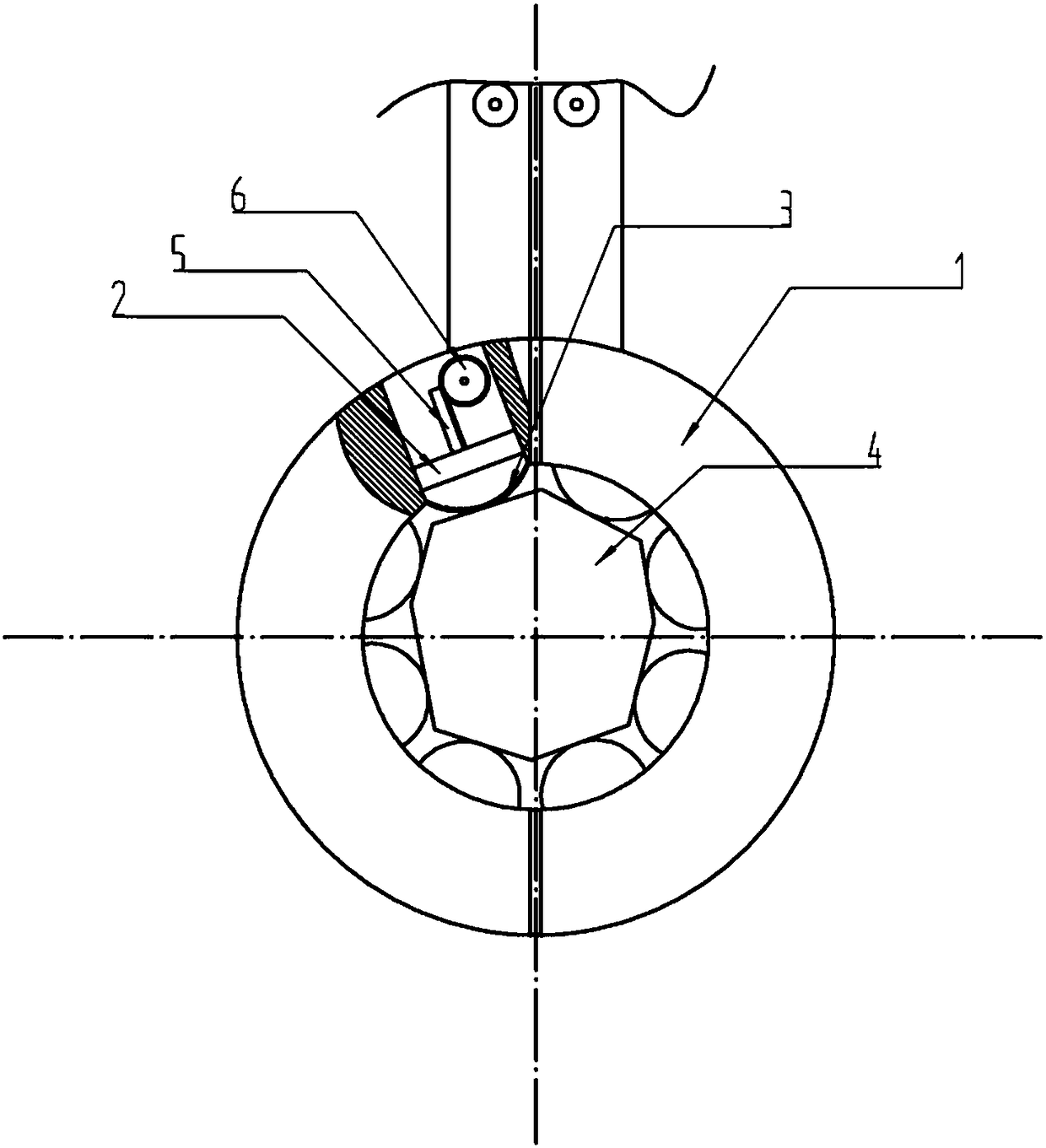
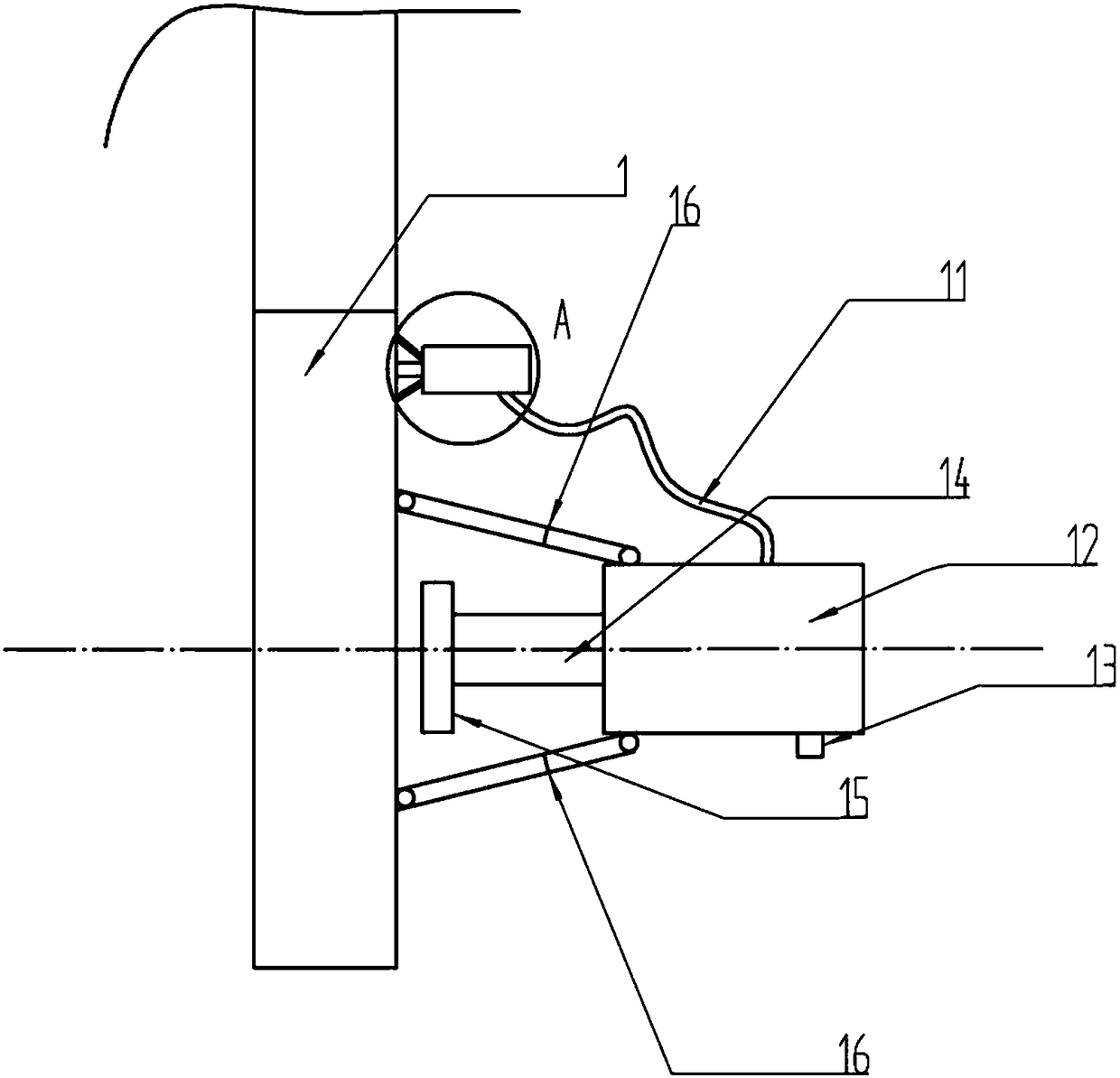
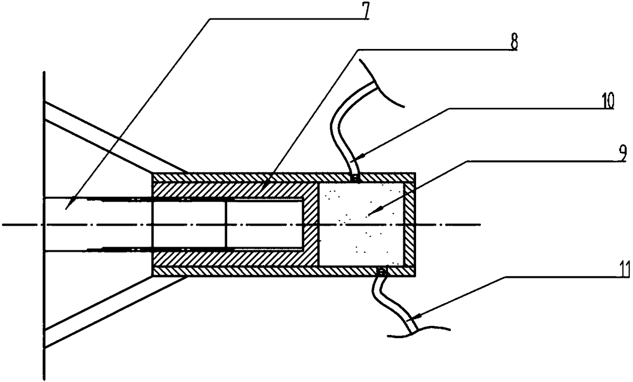
[0029] The reference signs in the drawings of the description include: clamp arm 1, piston 2, bottom 3, workpiece 4, rack 5, gear 6, rotating shaft 7, slider piston 8, liquid chamber 9, liquid inlet pipe 10, liquid outlet pipe 11. Telescopic hydraulic cylinder 12, liquid discharge valve 13, piston rod 14, push plate 15, telescopic rod 16.
[0030] The embodiment is basically as attached figure 1 Shown:
[0031] The industrial robot gripper includes a gripping part, which is ring-shaped and formed by combining two semi-circular gripping arms; it also includes a driving part that drives the opening and closing of the gripping part. The available form of the drive is not Many of them are in the prior art, so I won’t go into details here; there are a plurality of sliding chambers evenly distributed in the inner circumference of the clamp arm, and the bottom 3 of the sliding chamber is ...
PUM
 Abstract
Description
Claims
Application Information
 - R&D
- Intellectual Property
- Life Sciences
- Materials
- Tech Scout
- Unparalleled Data Quality
- Higher Quality Content
- 60% Fewer Hallucinations
Browse by: Latest US Patents, China's latest patents, Technical Efficacy Thesaurus, Application Domain, Technology Topic, Popular Technical Reports.
© 2025 PatSnap. All rights reserved.Legal|Privacy policy|Modern Slavery Act Transparency Statement|Sitemap|About US| Contact US: help@patsnap.com


